Needle nailing force self-adjusting energy-storage clamp-shaped stapler

An energy storage type, stapler technology, applied in binding and other directions, can solve the problems of limited space for human hands, increased force arm, limited structure space, etc., to achieve obvious labor-saving effect, prolong working life, and high binding efficiency.

Inactive Publication Date: 2008-07-30
廖金志
View PDF0 Cites 6 Cited by
  • Summary
  • Abstract
  • Description
  • Claims
  • Application Information

AI Technical Summary

Problems solved by technology

Its technical disadvantages are respectively: 1. The force-transmitting structure is not much labor-saving, and it takes a lot of force to implement the staples in the hand, and the hand feels uncomfortable, so it can only be used on small and medium-sized staplers for binding 1 to 45 sheets of paper
2. Due to the limitation of the holding space of the human hand, the existing pliers-type stapler cannot increase the force arm by excessively lengthening the handle, so the structural space for improvement is very limited

Method used


Image

  • Needle nailing force self-adjusting energy-storage clamp-shaped stapler
  • Needle nailing force self-adjusting energy-storage clamp-shaped stapler
  • Needle nailing force self-adjusting energy-storage clamp-shaped stapler

Examples


Embodiment 1

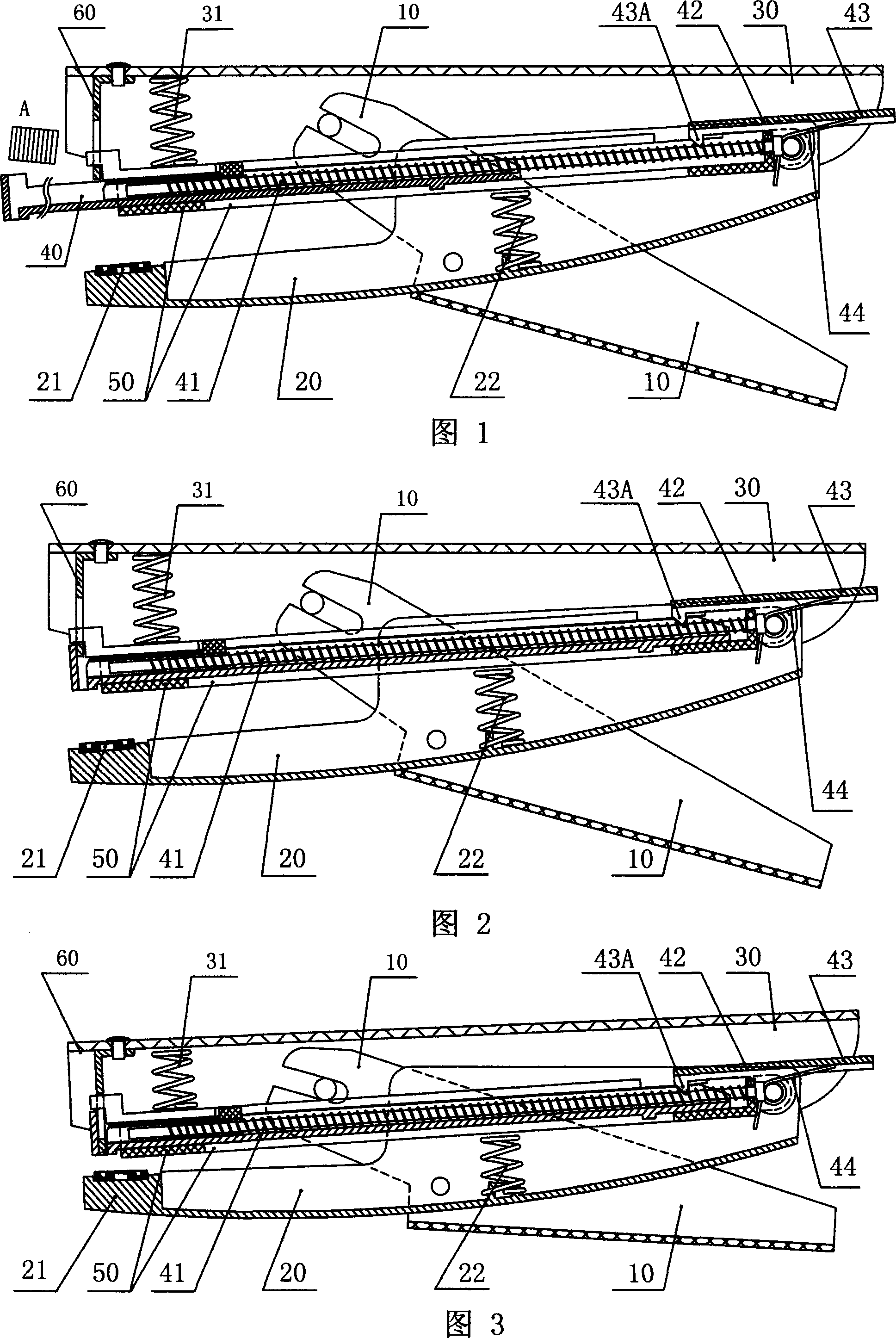
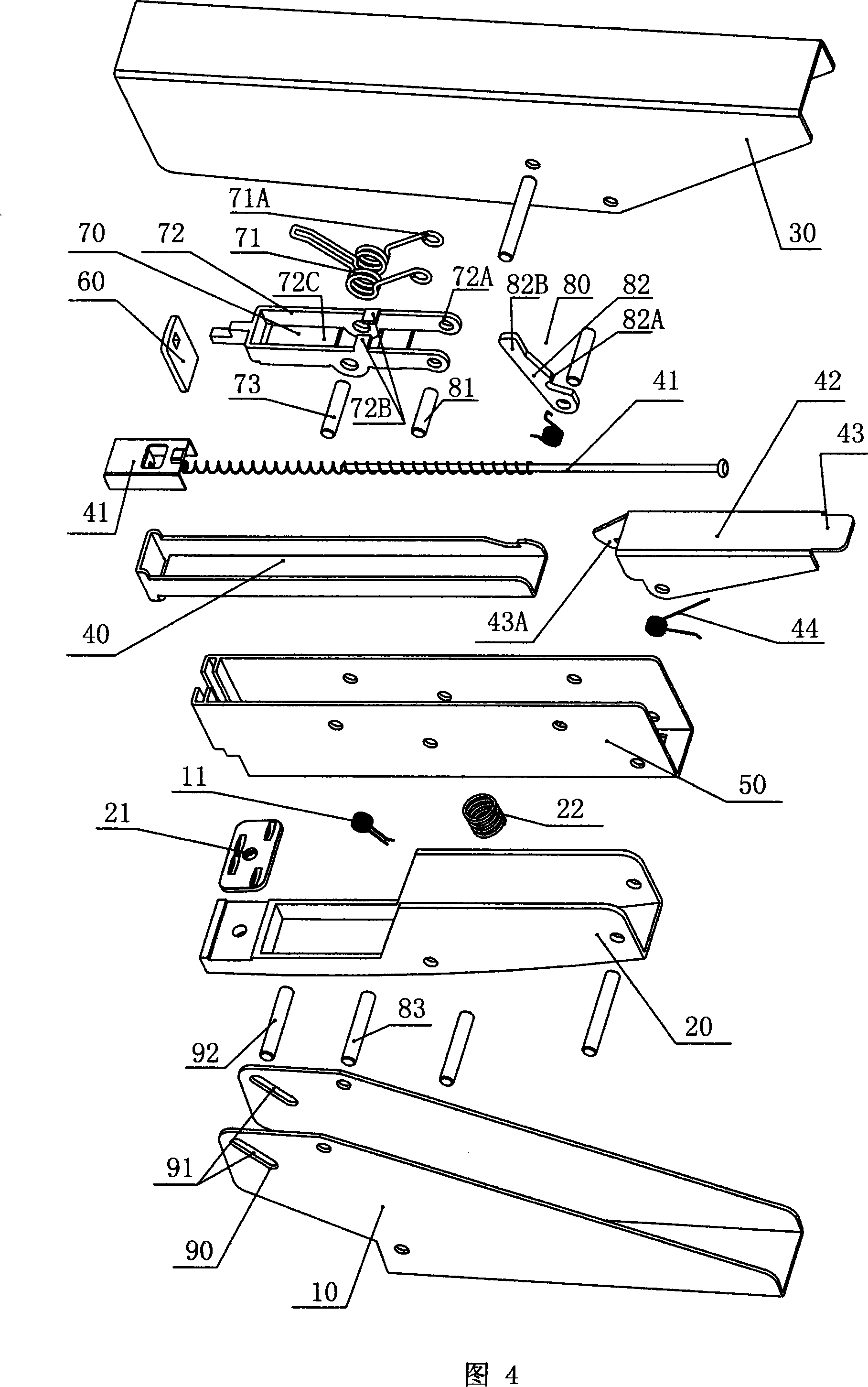
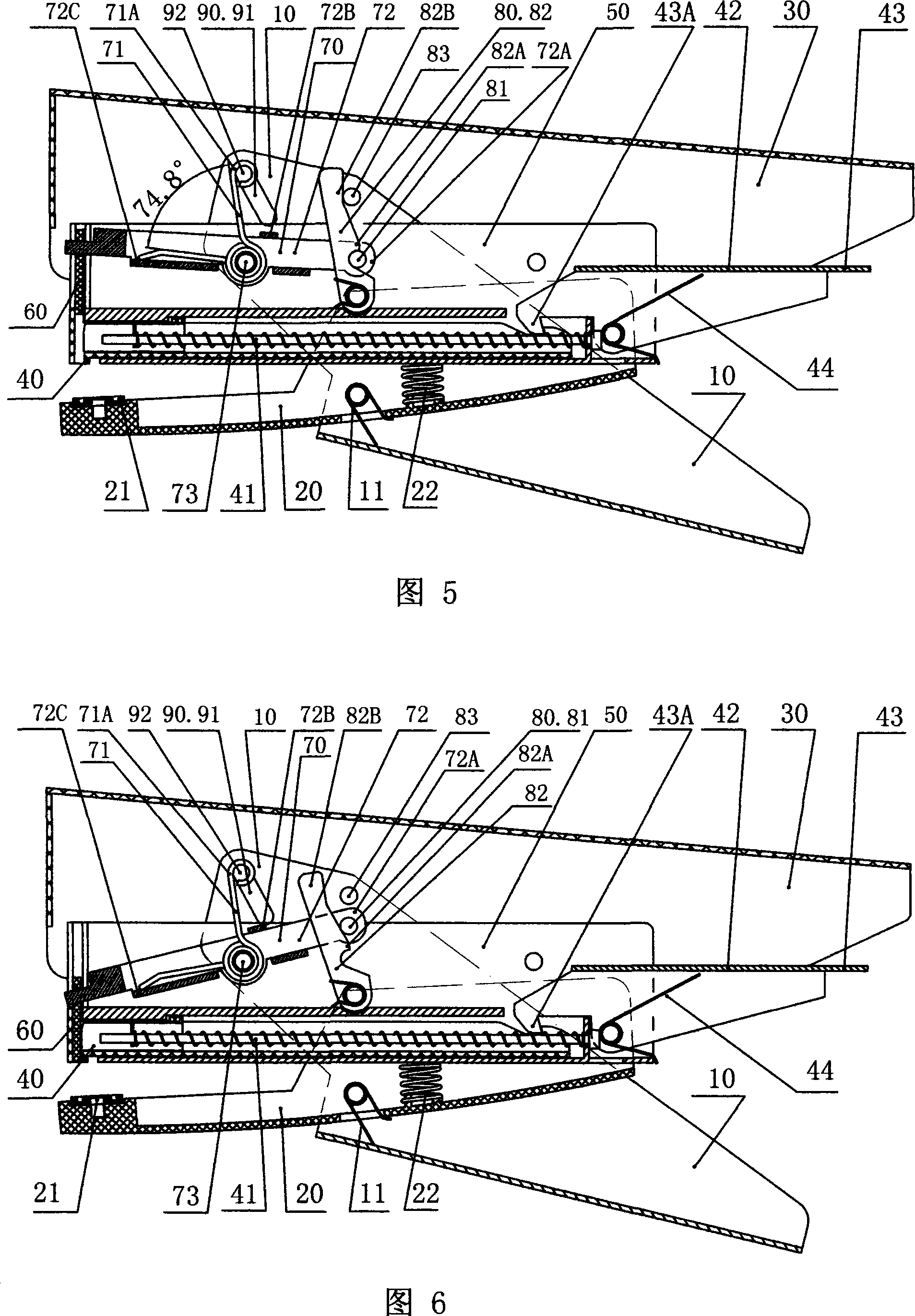
[0047] Figures 4 to 8 show the three-dimensional schematic diagram of the dismantled structure of Embodiment 1 of the energy storage type pliers-type stapler of the present invention, and the cross-sectional view of the assembly structure when the thick paper and thin paper are pressed tightly and the nails are operated. schematic diagram. Embodiment 1 includes a handle 10, a base 20, an upper cover 30, a box 50 with an elastic needle pusher 41 or a book needle slot 40 slidably fitted therein, and a staple sheet for pressing the book needle A on the end of the elastic needle pusher 41 60, on the base 20, a needle plate 21 is provided at the position where the corresponding nail sheet 60 falls, and a bottom spring 22 is also provided on the base 20; the box 50 is hinged at the rear of the base 20, The upper cover 30 is on the box 50, the upper cover 30 and the box 50 are coaxially hinged on the base 20, the middle part of the handle 10 is hinged on the middle part of the base 2...

Embodiment 2

[0056] Figures 9 to 13 are the three-dimensional schematic diagrams of the disassembled structure of Embodiment 2 of the energy storage type pliers-type stapler of the present invention, and the cross-sectional schematic diagrams of the assembled structure when pressing thick paper and thin paper and performing staple operations. The structure of embodiment 2 is basically the same as that of embodiment 1, but the following structure is different from embodiment 1: that is, the lock head 81 is arranged on the outer section of the limit lever 72 that deviates from the hinge axis 73 .

[0057] Figures 10 and 11 are respectively schematic cross-sectional views of the assembled structure in Embodiment 2 when the thick paper is pressed tightly and the staples are operated. It can be seen from the figure that due to the support of thick paper, the driving lever 83 on the top of the handle 10 is at the lower position of the switch paddle 82B, and the power transmission shaft 92 on the ...

Embodiment 3

[0060] Figures 14 to 18 are the three-dimensional schematic diagrams of the disassembled structure of Embodiment 3 of the energy-storage pliers-type stapler of the present invention, and the cross-sectional schematic diagrams of the assembled structure when pressing thick paper and thin paper and performing staple operations. The structure of embodiment 3 is basically the same as that of embodiment 2, but the following structure is different from that of embodiment 2: that is, the firing outer end of the torsion spring 71 is directly hooked on the nail plate 60 .

[0061] Figures 15 and 16 are respectively schematic cross-sectional views of the assembly structure in embodiment 3 when the thick paper is pressed tightly and the nails are operated. It can be seen from the figure that due to the support of thick paper, the driving lever 83 on the top of the handle 10 is at the lower position of the switch paddle 82B, and the power transmission shaft 92 on the top of the handle 10 m...


PUM


Abstract

The invention relates to an energy-storing clip-on stapler with self-adjusting staple force, which consists of a handle, a pedestal, a top head, a box which sliding coordinates with a sliding elastic staple-pushing device or a staple groove and a staple sheet. Middle part of the handle is articulated with the middle part of the pedestal; an elastic energy-storing device and an energy-releasing switch are arranged between space of the box and / or the top head; the elastic device consists of a spring with an elastic percussion external end; the elastic percussion external end is directly or indirectly hook connected or articulated with the staple sheet; a energy-storing regulating part which can convert lifting distance between the pedestal and the staple groove into a corresponding displacement value of the spring is arranged on top of the handle; the regulating part and a specific part of the elastic energy-storing device and / or a specific part of the energy-releasing switch form a cooperative relation. The clip-on stapler of the invention has the advantages of effort-saving of the staple and good effect, and the invention can prolong the service life, automatically adjust the staple force according to thickness of the paper to be bound and save effort to bind tissue without damaging the paper.

Description

technical field [0001] The present invention relates to an office stationery, more specifically, the present invention relates to a stapler. Background technique [0002] The common structural features of the traditional pliers stapler are: the staple piece is fixed on the upper cover, when the handle and the tail of the upper cover are applied with force, the handle drives the upper cover to rotate counterclockwise downward under force, and at the same time the handle drives The base rotates upwards and clockwise under force, and the staple sheet moves downward synchronously with the upper cover, and the staple sheet then presses the book needles downward out of the book needle slot to realize the function of stapling. Take the ordinary needle slot pop-up pliers stapler as an example, as shown in Figure 1-3, its working process is as follows: [0003] To operate the traditional needle slot pop-up pliers type stapler, firstly, as shown in Figure 1, make the staple slot pop ...

Claims


Application Information

Patent Timeline
Patent Type & Authority Applications(China)
IPC IPC(8): B42B4/00
Inventor 廖金志
Owner 廖金志
Why Eureka
Try Eureka