
Image-forming device capable of positioning developing unit and developer cartridge precisely

A technology of developing unit and developer cartridge, which is applied in the direction of electric recording process applying charge pattern, equipment for applying electric recording process of charge pattern, electric recording technique, etc.

Active Publication Date: 2008-07-30
BROTHER KOGYO KK
View PDF0 Cites 5 Cited by
  • Summary
  • Abstract
  • Description
  • Claims
  • Application Information

AI Technical Summary

Problems solved by technology

[0007]Similarly, if the developing unit is manufactured to be replaceable like the toner cartridge, the same questions about the replaceability or convenience of the developing unit may arise

Method used


Image

  • Image-forming device capable of positioning developing unit and developer cartridge precisely
  • Image-forming device capable of positioning developing unit and developer cartridge precisely
  • Image-forming device capable of positioning developing unit and developer cartridge precisely

Examples


Embodiment Construction

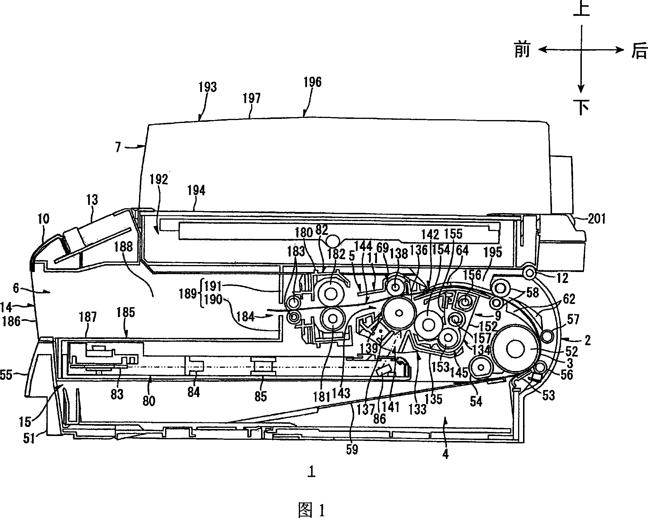
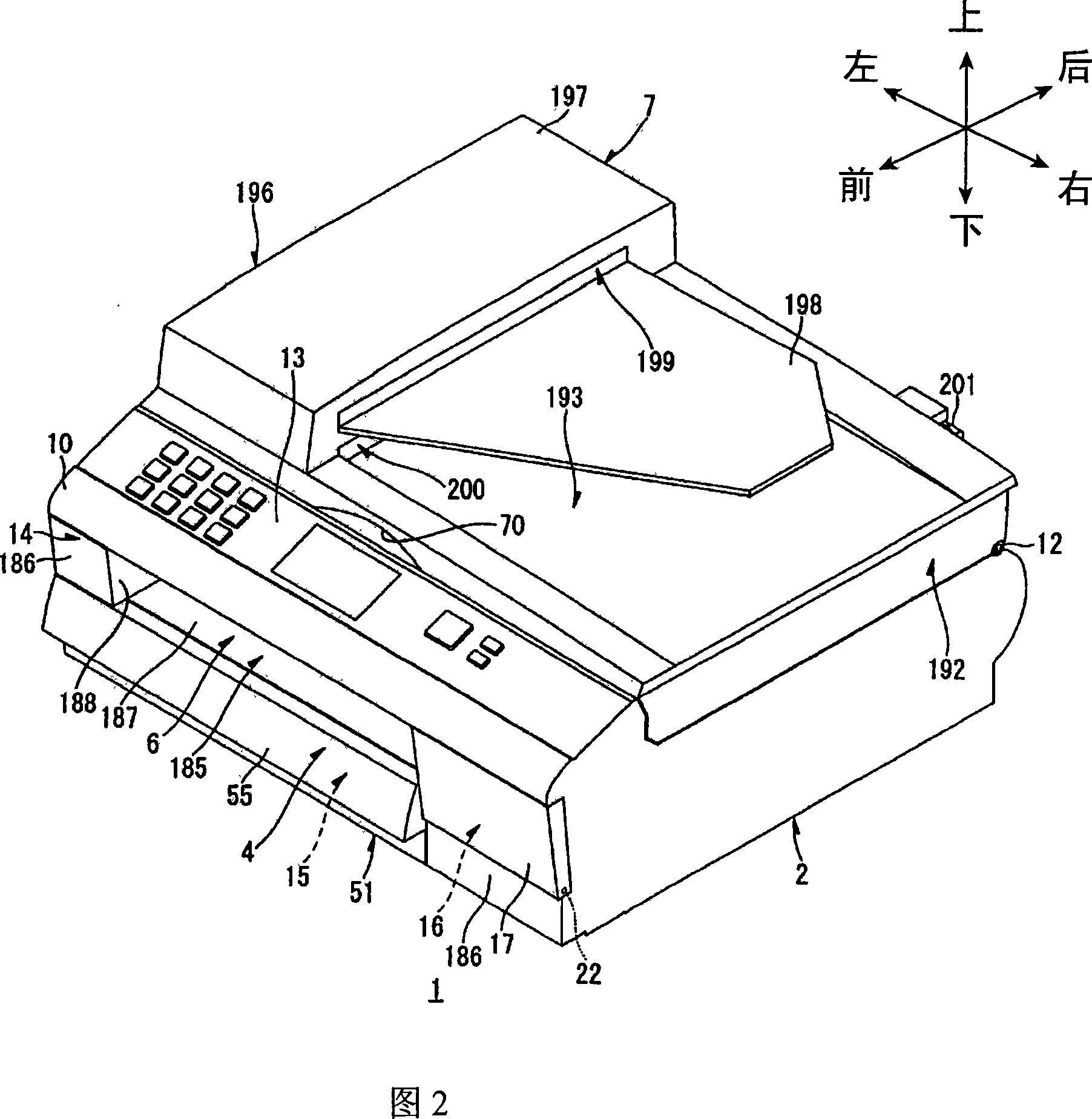
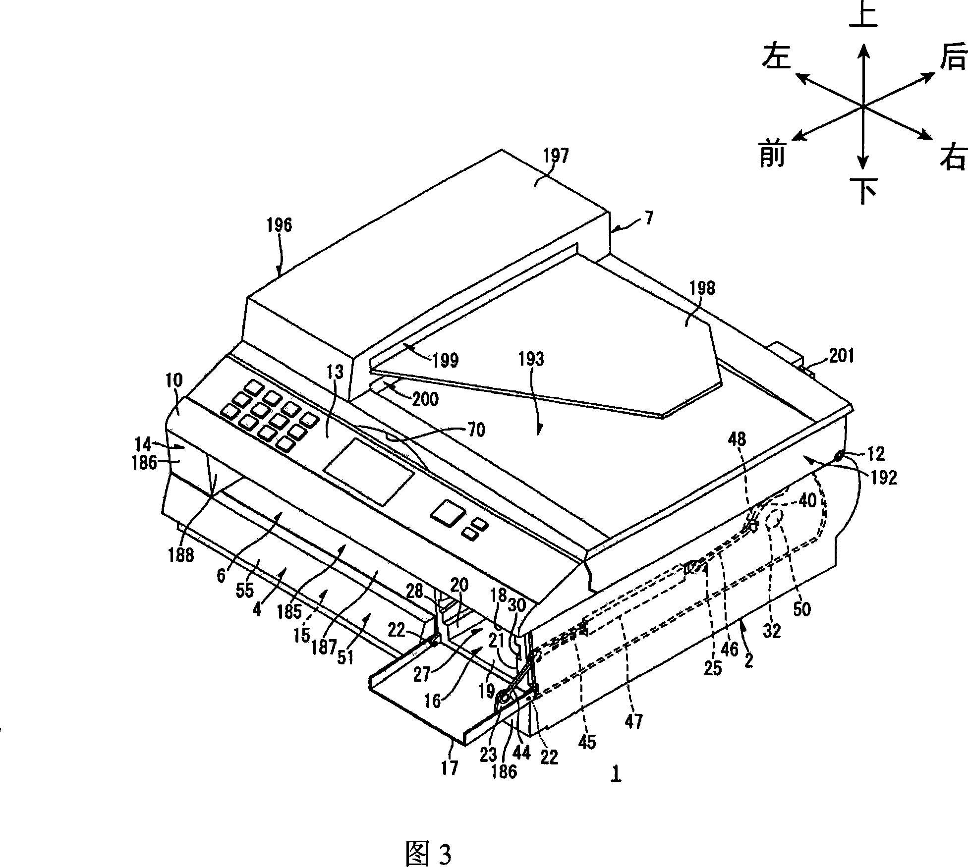
[0064] As shown in FIG. 1, a laser printer 1 includes a main casing 2, and a feeding unit 4 and an image forming unit 5 arranged in the main casing 2, a discharge unit 6 formed on the main casing 2, and a Scanning unit 7 above body 2.

[0065] A feeding unit 4 is installed in the main casing 2 for feeding paper. An image forming unit 5 is installed in the main casing 2 to form an image on paper supplied from the feeding unit 4 . A scanning unit 7 is arranged in the main casing 2 to scan image data on an original.

[0066] In the ensuing explanation, the left side in FIG. The right side in 1 is referred to as "rear side". Further, the near side in FIG. 1 will be referred to as "right side", and the far side in Fig. 1 will be referred to as "left side". The right-to-left direction will be referred to as the "width direction".

[0067] As shown in FIGS. 1 and 2 , the main casing 2 is formed to have a hollow substantially box shape. The top wall 10 has a substantially rectan...


PUM


Abstract

An image-forming device includes a casing, a process unit, a first shutter, a toner cartridge, a second shutter, and a wall. The process unit is detachably mounted in the casing and formed with a first opening, the process unit having a developer roller carrying a toner. The first shutter opens and closes the first opening. The toner cartridge is detachably mounted in the casing, accommodates the toner, and is formed with a second opening, the second opening being in alignment with the first opening. The second shutter opens and closes the second opening. The wall is disposed between the developer unit and the toner cartridge and is formed with a third opening, the third opening being in alignment with the first opening and the second opening. By providing the wall, the process unit and toner cartridge can be detachably mounted in the casing, thereby avoiding a drop in precision for positioning the process unit and toner cartridge relative to the casing.

Description

[0001] Cross-references to related applications [0002] This application claims the priority of Japanese Patent Application No. 2006-356438 filed on December 28, 2006 and Japanese Patent Application No. 2006-356439 filed on December 28, 2006. The entire contents of these prior applications are incorporated herein by reference. technical field [0003] The present application relates to an image forming apparatus, such as a laser printer. Background technique [0004] Generally, laser printers and other electrophotographic image forming apparatuses include a developing roller for carrying toner, and a toner cartridge containing toner to be supplied to the developing roller. As an example of a laser printer, Japanese Unexamined Patent Application Publication No. HEI-10-78697 discloses an image forming apparatus including a photosensitive member disposed around the photosensitive member to sequentially perform charging, exposure, and The image forming member of the developin...

Claims


Application Information

Patent Timeline
Patent Type & Authority Applications(China)
IPC IPC(8): G03G15/08G03G21/18
Inventor 佐藤正吾
Owner BROTHER KOGYO KK
Learn More