
Method for transporting irradiation object and irradiation device of electron accelerator

A technology for electron accelerators and irradiation devices, applied in the direction of DC voltage accelerators, electrical components, accelerators, etc., can solve the problems of low efficiency, large investment, and inability to make full use of electron accelerators, so as to ensure the quality of irradiation and improve irradiation efficiency effect

Active Publication Date: 2008-07-30
CGN DASHENG ELECTRON ACCELERATOR TECH
View PDF0 Cites 2 Cited by
  • Summary
  • Abstract
  • Description
  • Claims
  • Application Information

AI Technical Summary

Problems solved by technology

[0008] Under certain circumstances, the first transmission frame mentioned above, the second transmission frame and the two transmission methods make the irradiated object form a single-layer or double-layer structure under the irradiation window, which cannot make full use of the energy of the electron accelerator. The irradiation speed is slow and the efficiency is low; the third type of transmission frame requires two sets of irradiation processing devices, which requires a large investment and requires sufficient space in the irradiation room

Method used


Image

  • Method for transporting irradiation object and irradiation device of electron accelerator
  • Method for transporting irradiation object and irradiation device of electron accelerator
  • Method for transporting irradiation object and irradiation device of electron accelerator

Examples


Embodiment Construction

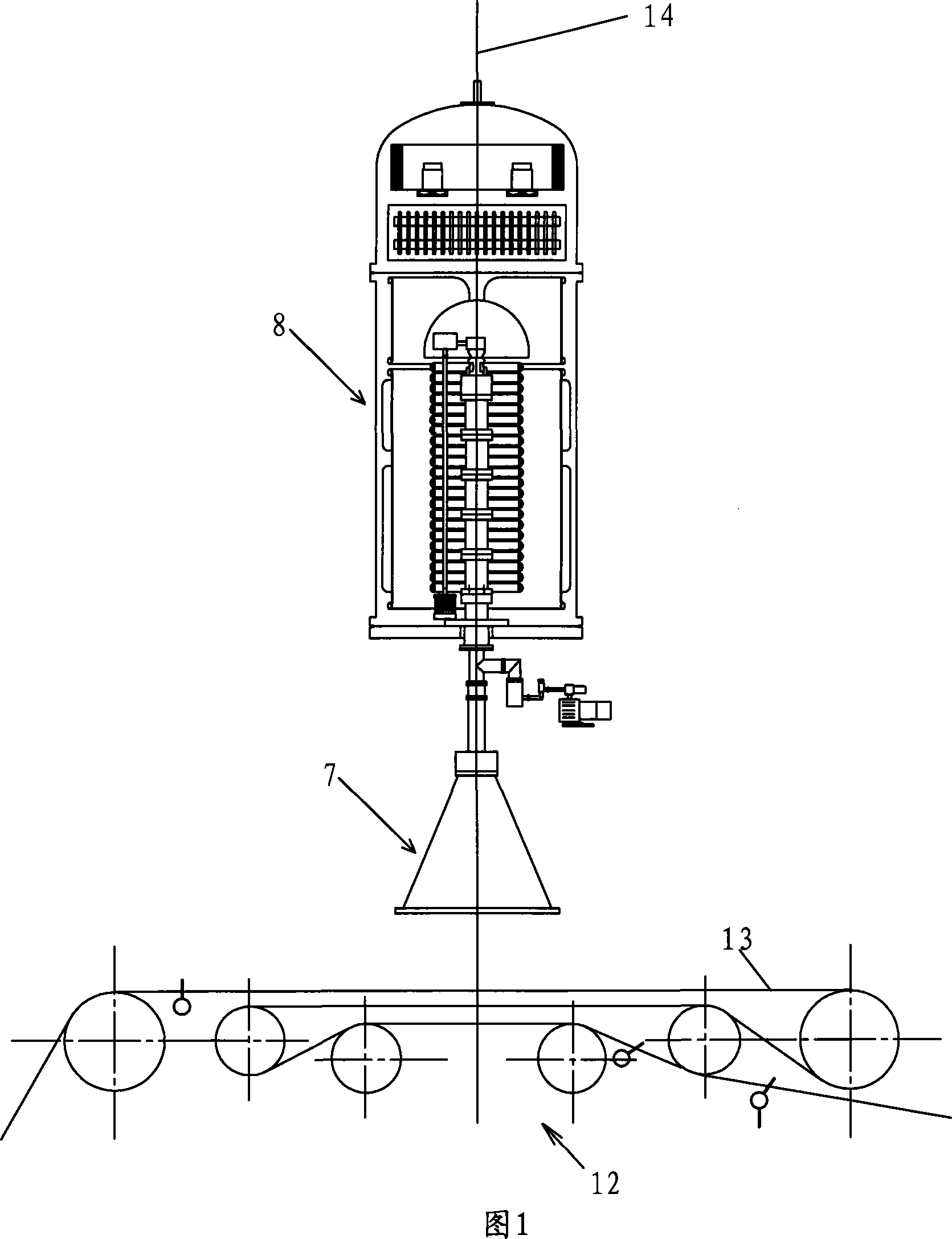
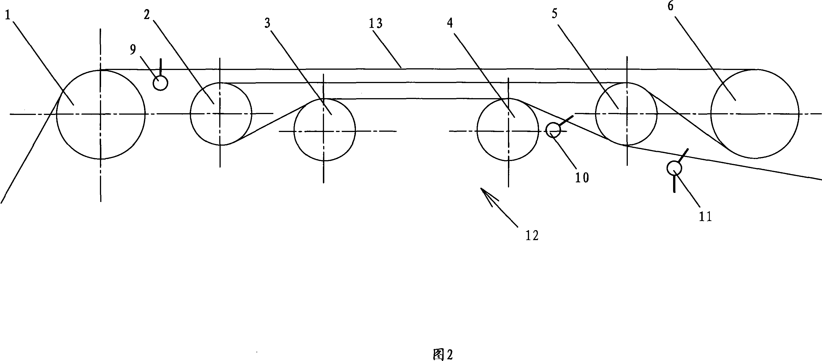
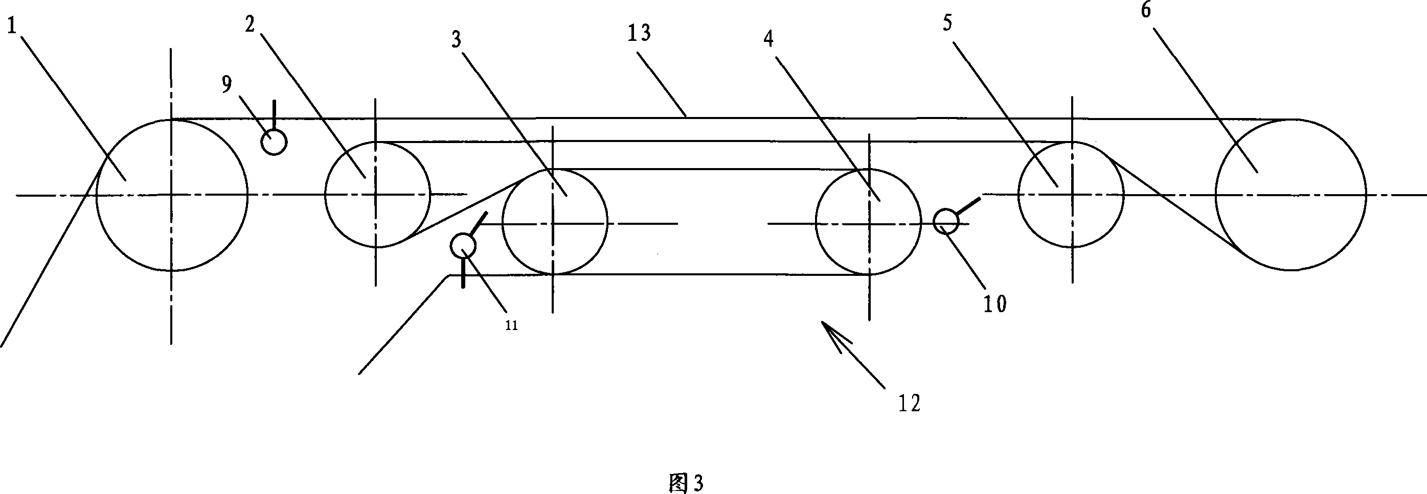
[0020] The electron accelerator irradiation device as shown in Figure 1 comprises an electron accelerator 8, an irradiation window 7 connected to the lower end of the electron accelerator 8, and a transmission frame 12 arranged below the irradiation window 7, and the electron accelerator 8 defines an axis line 14 The plane extending along the front-to-back direction where the axis line 14 is located is defined as a vertical plane, and the transmission frame 12 includes a first roller 1 and a second roller 2 arranged on one side of the vertical plane, The fifth roll 5 and the sixth roll 6, the distance between the first roll 1 and the vertical plane is greater than the distance between the second roll 2 and the vertical plane, and the distance between the sixth roll 6 and the vertical plane is greater than the distance between the fifth roll 5 and the vertical plane. The distance of the vertical plane, the first roller 1 and the sixth roller 6 are arranged on the same level, and...


PUM


Abstract

The invention relates to an electron accelerator irradiation plant, which comprises an electron accelerator, an irradiation window which is connected on the lower terminal of the electron accelerator, and a transmission shelf which is arranged on the lower part of the irradiation plant. The electron accelerator definition has an axial lead; the surface on which the axial lead extends forwards and backwoards is defined as a vertical plane, and the axial lead is located on the surface; the transmission shelf comprises a first roller and a second roller arranged on one side of the vertical plane, and a fifth and sixth roller arranged on the other side of the vertical plane. The distance between the first roller and the vertical plane is greater than that between the second roller and the vertical plane; the distance between the fifth roller and the vertical plane is greater than that between the sixth roller and the vertical plane; the first roller and the sixth roller are arranged at the same horizontal height; the second roller and the fifth roller are arranged at the same horizontal height; the transmission shelf further comprises a third roller and a forth roller arranged on the two sides of the vertical plane; the axial leads of the rollers are arranged in parallel. Three or four layers of irradiated objects are formed under the irradiation window; the invention has the advantages that the energy of electron accelerator is fully utilized, the energy is saved, the consumption is reduced, the benefit is improved, etc.

Description

technical field [0001] The invention relates to an electron accelerator irradiation device. The invention also relates to a transmission method of irradiating substances on the electron accelerator irradiation device. Background technique [0002] In the prior art, the electron accelerator irradiation device includes an electron accelerator, an irradiation window connected to the electron output end of the electron accelerator, and a transmission frame arranged at the lower part of the irradiation window. The electron accelerator is used to generate an electron beam with a certain beam intensity. The beam irradiates through the irradiation window on the irradiant wound on the transmission frame, changing the characteristics of the irradiant. [0003] In the prior art, the drive frames used for electron accelerator irradiation devices mainly include the following three forms: [0004] 1. Two rollers are used, and the irradiated material is wound on the two rollers in an ∞ s...

Claims


Application Information

Patent Timeline
Patent Type & Authority Applications(China)
IPC IPC(8): H05H5/02
Inventor 俞章华叶启捷朱焕铮
Owner CGN DASHENG ELECTRON ACCELERATOR TECH
Learn More