Reflection efficiency detection device for reflection magnet for radiation

A technology of reflection efficiency and detection device, which is applied in the direction of measuring device, material analysis using radiation diffraction, material analysis using wave/particle radiation, etc., can solve problems such as complex structure of equipment, armor deformation, huge equipment, etc., to ensure Effect of Irradiance Quality

Pending Publication Date: 2017-12-01
CGN DASHENG ELECTRON ACCELERATOR TECH
View PDF4 Cites 0 Cited by
  • Summary
  • Abstract
  • Description
  • Claims
  • Application Information

AI Technical Summary

Problems solved by technology

The structure of the equipment in the ∞-shaped irradiation method is complex, and the cable forms multiple turns on the transmission device under the beam, which increases the running resistance of the cable and easily causes the cable to stretch. If the armored cable is irradiated, the armor will deform and appear bamboo knot phenomenon
Since the simultaneous irradiation of two surfaces is not completed at one time during the irradiation process, the cable will also rotate during the transmission process, resulting in uneven doses on the upper and lower surfaces and affecting product quality
[0003] Because the traditional irradiation threading method has too many turns and too much resistance, especially when irradiating large-diameter cables, cable sheaths or hard tubes that are not easy to bend, the ∞-shaped irradiation method is used to irradiate indoor equipment. And the uniformity of irradiation and the utilization of beam current also decrease

Method used


Image

  • Reflection efficiency detection device for reflection magnet for radiation
  • Reflection efficiency detection device for reflection magnet for radiation
  • Reflection efficiency detection device for reflection magnet for radiation

Examples


Embodiment Construction

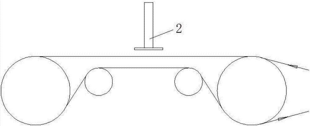
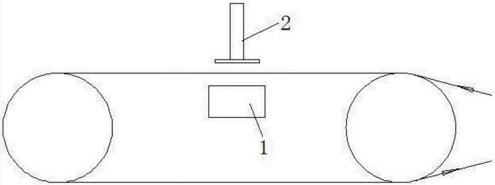
[0026] After irradiation with reflective magnets, the front and back of the cable are irradiated at the same time. As long as the reflection efficiency of the lower end electron beam is ensured, the uniformity of the front and back irradiation doses can be guaranteed, and the dose caused by the rotation of the cable during transmission is eliminated. Inhomogeneity. After the reflection magnet is installed in place, it is necessary to detect the reflection efficiency and adjust the parameters of the reflection magnet to achieve the highest reflection efficiency, so as to ensure the radiation quality of the cable. Aiming at detecting the reflection efficiency of a reflection magnet, the present invention provides a reflection efficiency detection device of a reflection magnet for irradiation to meet the detection requirements.

[0027] The technical solutions of the present invention will be clearly and completely described below through specific embodiments. Apparently, the de...


PUM

PropertyMeasurementUnit
diameteraaaaaaaaaa

Abstract

The invention relates to a reflection efficiency detection device for reflection magnet for radiation. An electronic accelerator scanning window is arranged above a reflection magnet, and the reflection efficiency detection device is arranged between the reflection magnet and the electronic accelerator scanning window through a mounting rack. The reflection efficiency detection device comprises a simulated cable unit, an electronic receiving unit and a detection unit, wherein one surface, facing to one side of the electronic accelerator scanning window, of the simulated cable unit is the front surface, and one surface, facing to one side of the reflection magnet, of the simulated cable unit is the rear surface; and electronic receiving units are arranged on the front surface and rear surface of the simulated cable unit and are connected with the detection unit. By stimulating a cable structure, current densities on upper and lower electronic receiving plates are detected; by making comparison on the current densities, the reflection efficiency is calculated; and by adjusting each parameter of the reflection magnet, the highest state of the reflection efficiency is realized, so that the radiation quality of a cable is guaranteed.

Description

technical field [0001] The invention relates to the technical field of industrial radiation processing, in particular to a reflection efficiency detection device of a reflection magnet for radiation. Background technique [0002] At present, the radiation processing technology of traditional wire and cable adopts the ∞-shaped bidirectional radiation method (see figure 1 As shown), that is, the wires and cables are wound and arranged in the shape of "∞" on the two reversing rollers, and are adjusted by the lifting wire, pressing wheel and (or) tensioning roller, so that the upper row of cables and the lower row of cables are in the spoke Passing under the window, the electron beam irradiates the upper half surface and the lower half surface of the cable respectively, and the cable is uniformly irradiated to the board during multiple reciprocating movements. The structure of the equipment in the ∞-shaped irradiation method is complex, and the cable forms multiple turns on the...

Claims


Application Information

Patent Timeline
Patent Type & Authority Applications(China)
IPC IPC(8): G01N23/20
CPCG01N23/20G01N2223/201G01N2223/052
Inventor 朱焕铮许森飞陆洁平朱晓
Owner CGN DASHENG ELECTRON ACCELERATOR TECH
Why Eureka
Try Eureka