Planetary gear multipath transmission stepless speed changer

A technology of continuously variable transmission and planetary gear, which is applied in the direction of gear transmission, transmission, differential transmission, etc., can solve the problems of unsatisfactory power performance, complex structure, low hydraulic transmission efficiency, etc., and achieve production cost and Low investment in equipment, simple auxiliary and servo systems, and less auxiliary and servo systems

Inactive Publication Date: 2008-08-06
龙宏元
View PDF0 Cites 19 Cited by
  • Summary
  • Abstract
  • Description
  • Claims
  • Application Information

AI Technical Summary

Problems solved by technology

[0003] Realizing continuously variable transmission is the goal that the automobile industry has been longing for. The current hydraulic automatic transmission and electronically controlled continuously variable transmission have made great progress to a certain extent, but they also have some shortcomings: 1. Hydraulic automatic transmission transmission The ratio is discontinuous, and it can only realize stepless speed change within the subsection range; the efficiency of hydraulic transmission is low, and the power performance and fuel economy are not ideal
2. Due to material reasons, electronically controlled continuously variable transmissions can only be used in some small-displacement vehicles at present, but cannot be applied in large-displacement and high-power vehicles.
3. They are complex in structure, high in production cost, and difficult to maintain
Because of the above reasons, the continuously variable transmission of automobiles has not been popularized.

Method used


Image

  • Planetary gear multipath transmission stepless speed changer
  • Planetary gear multipath transmission stepless speed changer
  • Planetary gear multipath transmission stepless speed changer

Examples


Embodiment 1

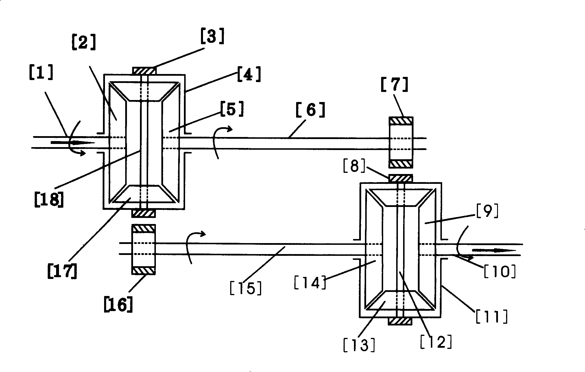
[0021] Example 1: Combining figure 1, in the input-stage differential, the half shaft bevel gear [2] is selected as the main input gear of the input-stage differential, and the warp shaft [1] is connected with the torque power, and the gear on the input-stage differential case [4] [ 3] and the other side bevel gear [5] of the input stage differential are used as two output gears of the input stage differential; any side bevel gear [9] of the output stage differential is used as the main output gear of the output stage differential , the shaft [10] drives the rear-stage transmission mechanism, and the gear [8] on the output-stage differential case [11] and the other half shaft bevel gear [14] of the output-stage differential are used as the two inputs of the output-stage differential gear. The output gear [5] of the input stage differential meshes with the input gear [8] of the output stage differential via the shaft [6] and the gear [7] on the shaft [6], forming a transmissio...

Embodiment 2

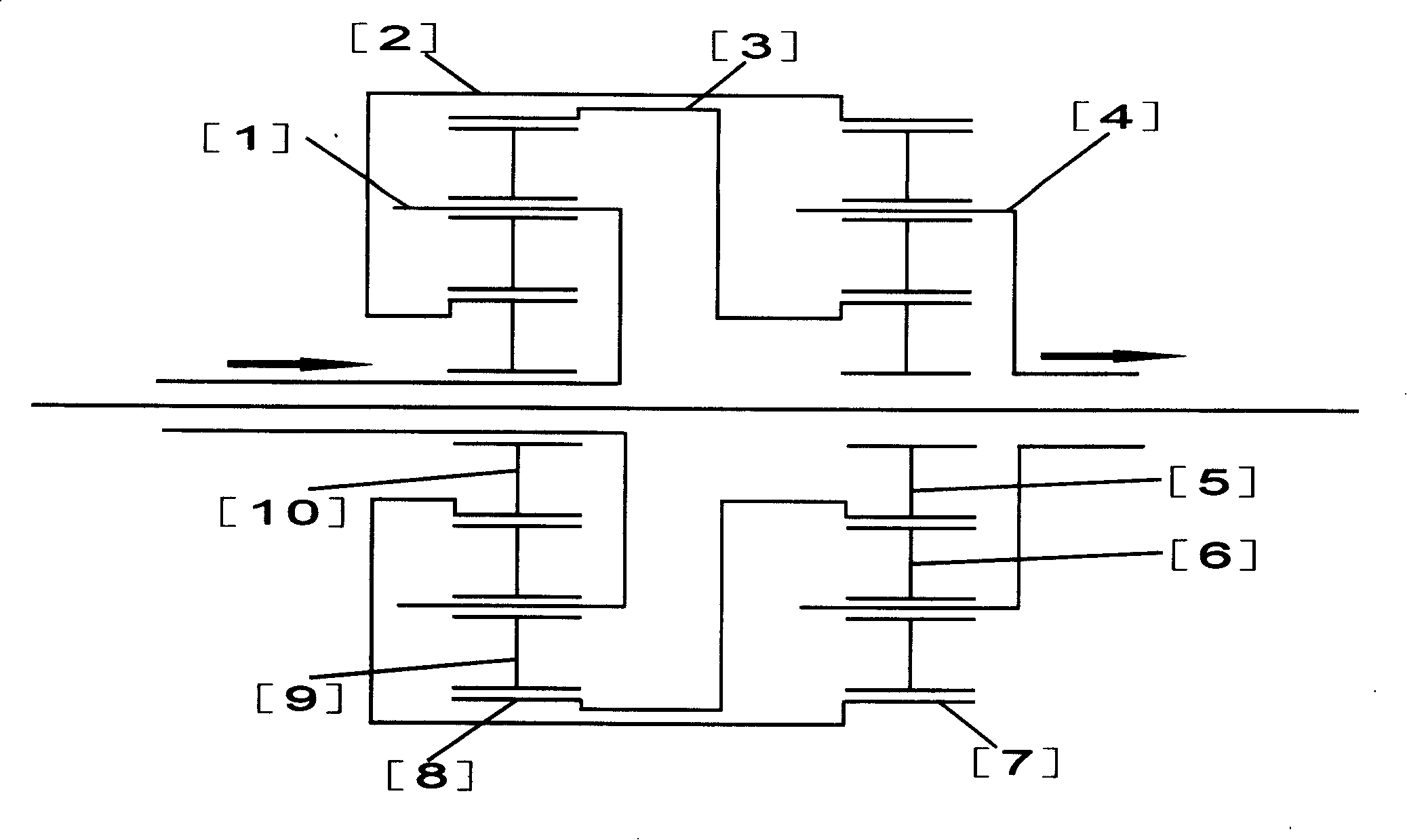
[0022] Example 2: Combining figure 2 , in the planetary gear mechanism of the input stage, the planetary carrier [1] is selected as the main input gear of the planetary gear mechanism of the input stage, connected with the torque power, and the sun gear [10] and the ring gear [8] of the planetary gear mechanism of the input stage are used As the two output gears of the input stage; in the output stage planetary gear mechanism, the planet carrier [4] is selected as the main output gear of the output stage planetary gear mechanism to drive the rear stage transmission mechanism, and the sun gear [4] of the output stage planetary gear mechanism is used 5] and the ring gear [7] as two input gears of the output stage. Use the output sun gear [10] of the input stage planetary gear mechanism and the input ring gear [7] of the output stage planetary gear mechanism to form the transmission path [2] of the input stage sun gear output stage ring gear for torque transmission. Torque-redu...

Embodiment 3

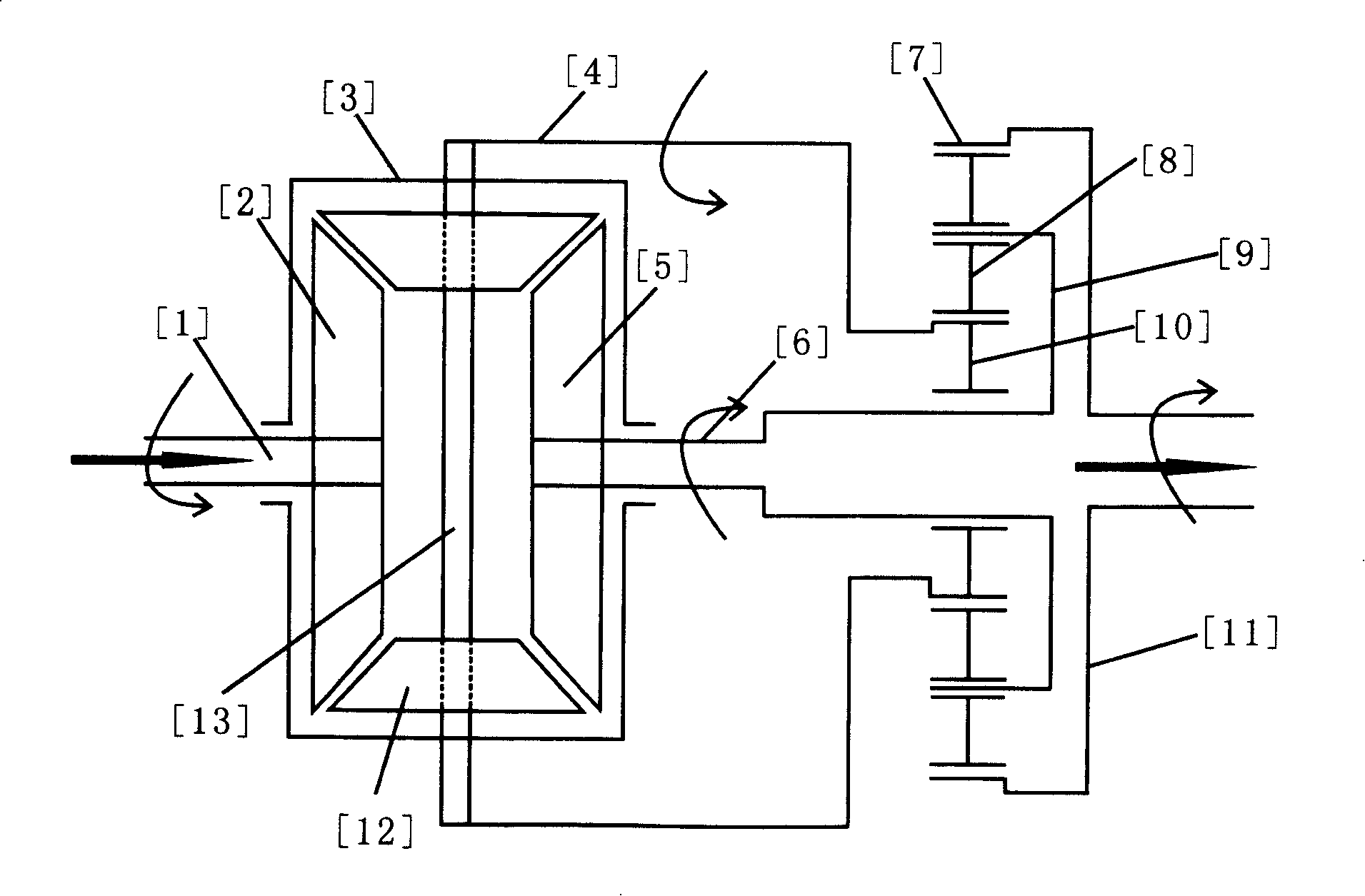
[0023] Example 3: Binding image 3 , use the differential as the input stage and choose the half-shaft bevel gear [2] as the main input gear of the input stage differential, connect the warp shaft [1] with the torque power, use the input stage differential case [3] and input The other half-shaft bevel gear [5] of the first-stage differential is used as the two output gears of the input-stage differential; the planetary gear mechanism is used as the output stage and the ring gear [7] is selected as the main output gear [11] of the output-stage planetary gear mechanism ], drive the back-stage transmission mechanism, and use the sun gear [10] and the planetary carrier [9] of the output stage planetary gear mechanism as the two input gears of the output stage. Use the output gear [5] of the input stage differential and the input planetary frame of the output stage planetary gear mechanism to form a path of torque transmission [6]. [3] and the input sun gear [10] of the output sta...


PUM


Abstract

The invention discloses a stepless transmission for planetary gear multi-path drive, which is designed according to the principle of differently distributing the moment and revolution rate because the planetary gear provides rotation and revolution to different extent under different environment and control. The invention is composed of two rotating members with planetary gear component, one set of the rotating members is used as input step and a rotating member is used to serve as a main input gear for connecting an input moment, and the other set is used as output step and a rotating member serves as a main output gear for driving rear-step driving mechanism. The middle of the other two rotating members of the input step and the output step are connected in pair by different drive ratio, thereby respectively forming two drive paths for reducing speed and increasing moment and increasing speed and reducing moment. Stepless change to driving of input moment is accomplished by forward and reverse rotation modes of the drive path for increasing speed and reducing moment, constantly variable rotating speed of the two moment driving paths and proper control to rotation speed of the two movement driving paths. The stepless transmission for planetary gear multi-path drive is a stepless transmission for gears with fixed number of teeth, has high drive efficiency and strong drive capacity, which is produced with prior art and products with low device investment, and has manufacturing cost much lower than existing stepless transmission and automatic transmission.

Description

[0001] Field of technology: [0002] The invention relates to a continuously variable transmission, in particular to a principle of different distribution of torque and rotational speed by revolution and rotation of planetary gears to realize stepless change of torque and rotational speed transmission. technical background: [0003] Realizing continuously variable transmission is the goal that the automobile industry has been longing for. The current hydraulic automatic transmission and electronically controlled continuously variable transmission have made great progress to a certain extent, but they also have some shortcomings: 1. Hydraulic automatic transmission transmission The ratio is discontinuous, and it can only realize stepless speed change within the subsection range; the hydraulic transmission efficiency is low, and the power performance and fuel economy are not ideal. 2. Due to material reasons, the electronically controlled continuously variable transmission can o...

Claims


Application Information

Patent Timeline
Patent Type & Authority Applications(China)
IPC IPC(8): F16H3/44F16H48/06
Inventor 龙宏元
Owner 龙宏元
Why Eureka
Try Eureka