Backlight module unit and backlight module

A technology for backlight modules and light sources, applied in the field of backlight module units and backlight modules, capable of solving the problems of large thickness of the backlight module 1 and increasing the overall size of liquid crystal display devices, etc.

Active Publication Date: 2008-08-06
AU OPTRONICS CORP
View PDF0 Cites 3 Cited by
  • Summary
  • Abstract
  • Description
  • Claims
  • Application Information

AI Technical Summary

Problems solved by technology

However, in this light mixing design structure, in order to improve the light mixing efficiency, it is necessary to increase the thickness of the light mixing space 10, so that the thickness of the backlight module 1 is too large, increasing the overall size of the liquid crystal display device

Method used


Image

  • Backlight module unit and backlight module
  • Backlight module unit and backlight module
  • Backlight module unit and backlight module

Examples


Embodiment Construction

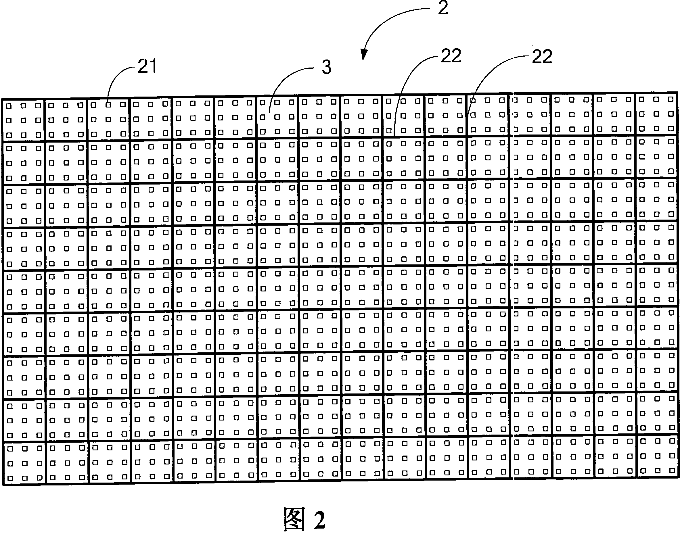
[0026] FIG. 2 is a diagram illustrating an embodiment of a backlight module according to the present invention. As shown in Figure 2, the backlight module 2 is applied to liquid crystal display devices or other purposes, and it includes a plurality of backlight module units 3, and these backlight module units 3 are arranged in an array, that is, the backlight module is formed in a continuous manner. 2. Each backlight module unit 3 includes a plurality of light sources 21 and a plurality of optical barriers 22, wherein the backlight module unit 3 is surrounded and defined by a plurality of optical barriers 22; however, due to the setting of the optical barriers 22, the light emitted by the light emitting diodes 21 illuminates When it is at the optical barrier 22, it will be reflected away from the optical barrier 22, resulting in dark bands on both sides of the optical barrier 22, and this dark band problem is especially obvious at large viewing angles, which affects the displa...


PUM


Abstract

The present invention relates to a backlight module unit and a backlight module. The backlight module unit comprises a first light source, a second light source and an optical barrier; light source spacing is formed between the second light source and the first light source, barrier spacing is formed between the optical barrier and the second light source. As the barrier spacing is actually less than half of the light source spacing, the backlight module unit has the characteristic of mixing light uniformity, and no dark lane is produced by setting of the optical barrier. Therefore, the backlight module comprising a plurality of the backlight module units also has the characteristics of no dark lane, mixing light uniformity and thin thickness.

Description

technical field [0001] The invention relates to a backlight module unit and a backlight module of a backlight module, in particular to a backlight module unit with a proper distance between a light source and an optical barrier and a backlight module using a plurality of the backlight module units. Background technique [0002] With the advancement of science and technology, liquid crystal display devices with power saving, low radiation, and thin size have gradually been widely used in various electronic products with display screens such as computers, mobile phones, and televisions in daily life. Compared with the traditional cathode ray tube display device, the liquid crystal display device requires an additional light source to assist imaging on the screen, and the additional light source is generally called a backlight module. [0003] In order to make LCD devices more power-saving, have a longer service life, and have more saturated colors, manufacturers have abandoned...

Claims


Application Information

Patent Timeline
Patent Type & Authority Applications(China)
IPC IPC(8): G02F1/13357F21K7/00F21V11/06G02F1/1335F21K99/00
Inventor 彭赐光彭中陈志光刘邦炫
Owner AU OPTRONICS CORP
Why Eureka
Try Eureka