Ball bearing switch and its making method

A technology of ball switches and balls, applied in electric switches, electrical components, circuits, etc., can solve the problems of poor movement stability, inconsistent movement, time-consuming assembly, etc., and achieve the effect of good movement stability and easy assembly

Active Publication Date: 2008-08-06
ONCQUE CORP
View PDF0 Cites 4 Cited by
  • Summary
  • Abstract
  • Description
  • Claims
  • Application Information

AI Technical Summary

Problems solved by technology

[0009] 1. In order to improve the quality of use, the ball 12 must have the same contact angle with each built-in taper 131, that is, each built-in taper 131 must be equal in height, but because the aforementioned terminal 13 is designed as an independent component, To respectively insert the aforementioned terminals 13 into the aforementioned through holes 141 and make each built-in tapered portion 131 flush so as to have the same abutment angle with the ball 12 actually has the disadvantages of complicated and time-consuming assembly steps.
[0010] Two, such as image 3 As shown, when the aforementioned built-in tapered portion 131 is uneven and there is a height difference I, the abutment angles of the ball 12 and the aforementioned built-in tapered portion 131 will be different, so that the ball 12 will be subject to side external force and roll. The action of the built-in taper 131 is not consistent with the aforementioned, and relatively has the disadvantage of poor action stability

Method used


Image

  • Ball bearing switch and its making method
  • Ball bearing switch and its making method
  • Ball bearing switch and its making method

Examples


Embodiment Construction

[0037] The ball switch and its manufacturing method according to the present invention will be described in detail below with reference to the accompanying drawings and preferred embodiments.

[0038] Before the present invention is described in detail, it should be noted that in the following description, similar elements are denoted by the same reference numerals.

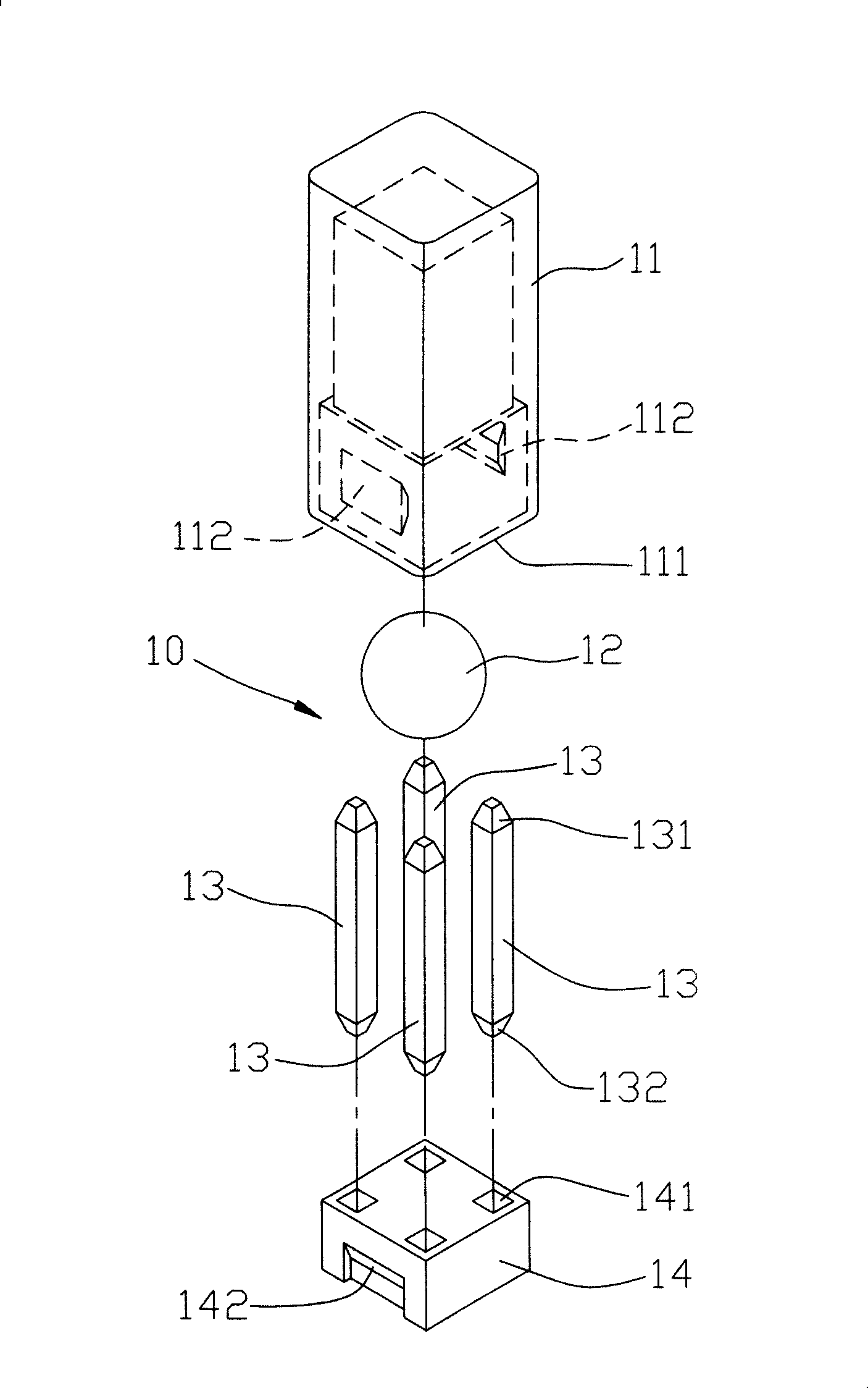
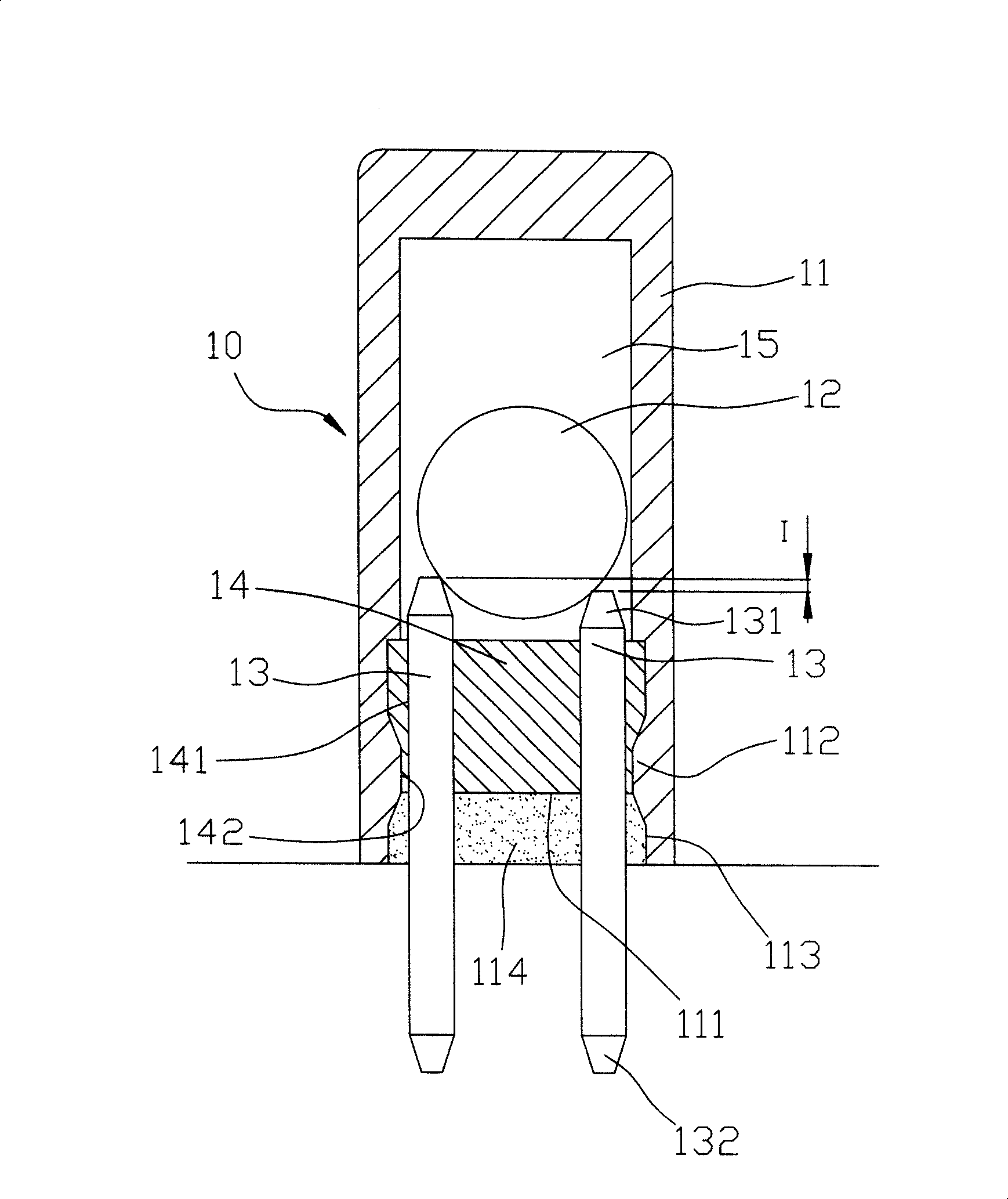
[0039] Such as Figure 4 , shown in FIG. 5 , the first preferred embodiment of the ball switch 2 of the present invention includes a first insulating shell 3 , a second insulating shell 4 , an insulating intermediate body 5 , two metal sheets 6 and a ball 7 .

[0040] As shown in Figure 5, Image 6 , Figure 7 As shown, the first insulating shell 3 is made of plastic molding, and is basically a square shape, with a first chamber 31 around an axis II and one end open, and two spaced apart from each other along the axis II A concave portion 32 and two convex portions 33 .

[0041] The second insulating shell 4 ...


PUM


Abstract

The invention provides a ball switch and a method for manufacturing the same, comprising a first insulation outer shell, a second insulation outer shell, an insulation central arrangement body, two metal sheets and a ball, wherein the insulation central arrangement body is provided with a first connection surface and a second connection surface which are opposite in direction; the first connection surface is used to be connected with the first insulation outer shell, and the second connection surface is used to be connected with the second insulation outer shell; the two metal sheets are arranged respectively between the first insulation outer shell and the insulation central arrangement body and between the second insulation outer shell and the insulation central arrangement body; the combination of the first insulation outer shell, the second insulation outer shell, the insulation central arrangement body and the metal sheets can limit a receiving space for receiving the ball, and the ball can move between a conduction connection position and a non-conduction connection position, thereby the ball switch has the advantages of relatively simple assembly and good action stability.

Description

technical field [0001] The invention relates to a ball switch, in particular to a ball switch with easy assembly and a manufacturing method thereof. Background technique [0002] Such as figure 1 , figure 2 As shown, the inventor previously designed and approved the ball vibration switch 10 of Taiwan No. 155965 patent, which includes an insulating sleeve 11, a ball 12 installed in the insulating sleeve 11, four metal terminals 13 and an insulating plug Block 14. [0003] The sleeve 11 is a rectangular columnar plastic tank with an opening 111 and two embedding protrusions 112 adjacent to the opening 111 and protruding from the inner ring surface. [0004] Each branch terminal 13 respectively has an inner taper portion 131 and an outer taper portion 132 in opposite directions. [0005] The insulating block 14 has four through holes 141 through which the terminals 13 pass, and two embedding recesses 142 provided on the outer ring surface for interfitting and combining wit...

Claims


Application Information

Patent Timeline
IPC IPC(8): H01H35/02H01H11/00
Inventor 周添铭
Owner ONCQUE CORP
Why Eureka
Try Eureka