Sound source separating device, speech recognizing device, portable telephone, and sound source separating method, and program

一种分离装置、音频识别的技术,应用在语音识别、频率/方向特性装置、语音分析等方向,能够解决性能下降、估计精度下降、自适应滤波器估计精度下降等问题,达到高分离性能、减少不舒服的噪声的效果

Inactive Publication Date: 2008-08-06
ASAHI KASEI KK
View PDF7 Cites 33 Cited by
  • Summary
  • Abstract
  • Description
  • Claims
  • Application Information

AI Technical Summary

Problems solved by technology

However, in GSC, there is a problem that when a target signal is transmitted from a direction deviated from the set target sound source direction, the target signal is canceled and degraded.
[0022] Therefore, in this adaptive filter operation, when both the target sound and the specific noise are audio, it is necessary to detect the state in which both are speaking, and the higher the frequency of both speaking, stop estimating the adaptive filter. The frequency of the filter increases, and as a result, there is a problem that the noise removal performance of the adaptive filter decreases
[0023] In addition, in the situation where large diffuse noise such as automobile running noise is generated, the estimation accuracy of the adaptive filter is reduced due to the influence of the diffuse noise. As a result, there is the following problem: The estimation accuracy of the speaker direction and the direction of arrival of the specific noise direction of the estimated filter parameters is reduced, and the overall performance of the system is reduced.
[0024] Furthermore, in the above-mentioned methods described in Patent Documents 6 and 7, when the noise component suppressing device is configured using a low-cost microphone for an automobile or the like, the initial reflection of the sound source in the vehicle is large, and the diffuse noise component is large. , The deviation of the microphone element used is large (about ±3db), the driver and the passenger speak at the same time, and there is a highly correlated target sound and specific noise at the same time, the adaptive filter unit does not perform the desired operation , cannot achieve the desired action as a whole

Method used


Image

  • Sound source separating device, speech recognizing device, portable telephone, and sound source separating method, and program
  • Sound source separating device, speech recognizing device, portable telephone, and sound source separating method, and program
  • Sound source separating device, speech recognizing device, portable telephone, and sound source separating method, and program

Examples


no. 1 Embodiment approach

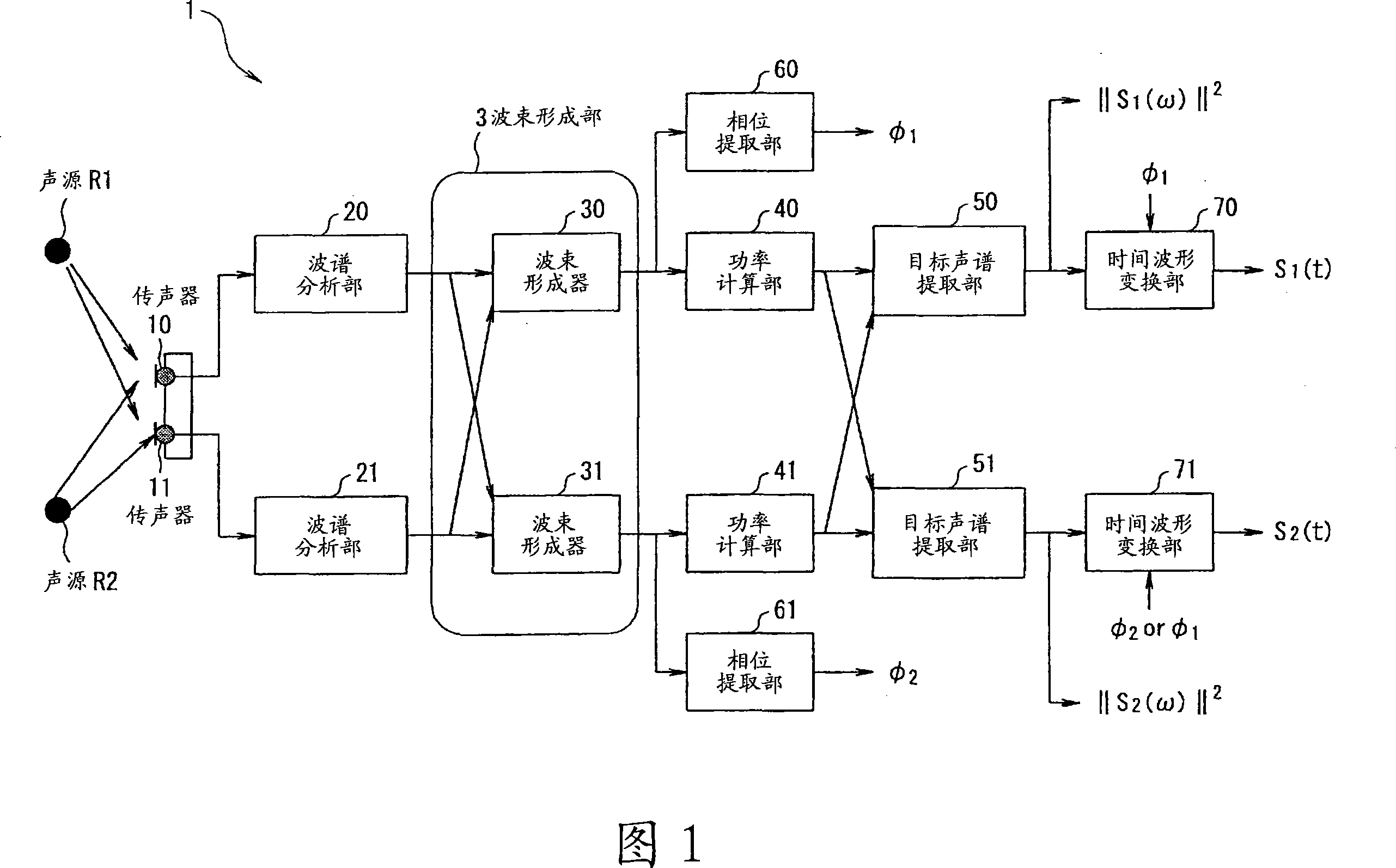
[0104] FIG. 1 is a diagram showing a basic configuration of a sound source separation system according to a first embodiment of the present invention. This system is composed of two microphones (hereinafter referred to as “microphones”) 10 and 11 and a sound source separation device 1 . The sound source separation device 1 has a CPU (not shown) for controlling the whole and executing arithmetic processing; hardware including storage devices such as ROM, RAM, and hard disk; and software including programs and data stored in the storage devices. The functional modules shown in Figure 1 are realized by these hardware and software.

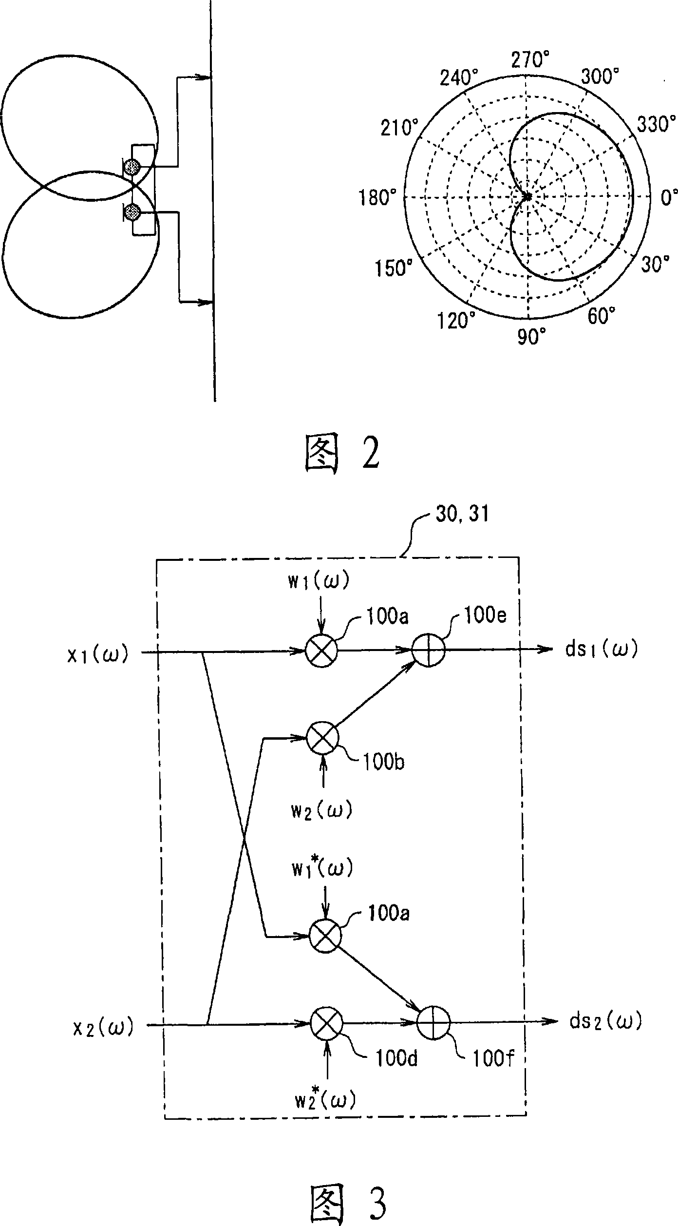
[0105] The two microphones 10 and 11 are omnidirectional microphones, and are installed at a distance of about several cm from each other on a plane. In addition, the microphones 10 and 11 are basically omnidirectional microphones, but a unidirectional microphone shown in FIG. 2 may also be used. The microphones 10, 11 receive signals from the two s...

no. 2 Embodiment approach

[0180] Next, a second embodiment will be described. FIG. 17 shows the configuration of a sound source separation system according to the second embodiment. In the first embodiment described above, first, the input from the microphones 10 and 11 is converted into frequency components by the spectrum analysis unit 20 and the spectrum analysis unit 21, but in this embodiment, first, the beamformer 80 The sum beamformer 81 generates a blind spot, generates a signal attenuating a signal from a specific direction of arrival, and converts it into a frequency component by the spectrum analysis unit 20 and the spectrum analysis unit 21 . In addition, in FIG. 17, the same code|symbol is attached|subjected to the part which has the same function as FIG. The configuration of the beamformer 80 and the beamformer 81 can be realized by performing filter processing configured in the form of an FIR filter shown in FIG. 18 or the like. At this time, the coefficients of the FIR filter can be o...

no. 3 Embodiment approach

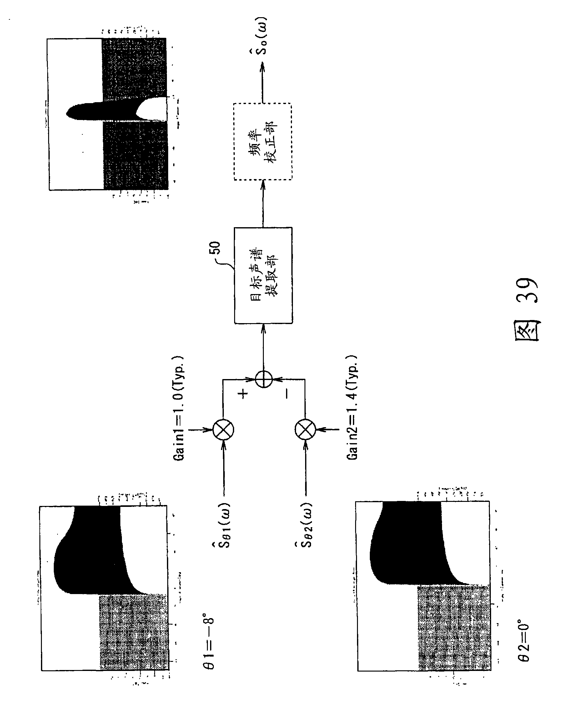
[0182] Next, a third embodiment will be described. 19 and 20 are diagrams showing the configuration of a sound source separation system according to a third embodiment. As described above, the target sound spectrum extraction unit 50 and the target sound spectrum extraction unit 51 shown in FIG. 1 and FIG. 17 are realized with the configuration shown in FIG. 5 , and perform sound source separation processing using the optimum threshold obtained through experiments. On the other hand, as shown in FIG. 8, the outputs of the difference calculation units 500, 510 in the target sound spectrum extraction units 50, 51, that is, dr i (ω)(i=1, 2) are in a point-symmetrical relationship with the front 0° as the center. Therefore, in the coefficient conversion units 501, 511 in the target sound spectrum extraction units 50, 51, if the threshold value is set to “0”, only the signs of the difference calculation units 500, 510 are looked at. The power spectrum information of the sound sou...


PUM


Abstract

The sound source signal from a target sound source is separated from the mixed sound in which the sound source signals from sound sources are mixed without being influenced by the variations of the sensitivity of microphone elements are provided. A beam former section (3) of the sound source separating device (1) performs beam formation to attenuate the sound source signals arriving from directions symmetrical with respect to the vertical line of the line connecting two microphones (10, 11) by spectrum-analyzing the output signals from the microphones (10, 11) and multiplying the signals after the spectrum analysis by the weighting factors complex conjugated with the signals. Power calculating sections (40, 41) calculate power spectrum information. Target sound spectrum extracting sections (50, 51) extract spectrum information on target sound sources according to the difference between the power spectrum information from one beam former and that from the other.

Description

technical field [0001] The present invention relates to a sound source separating device for separating a sound source signal coming from a target sound source using a plurality of microphones, a plurality of audio signals emitted from a plurality of sound sources, or a signal mixed with a plurality of sound signals such as various environmental noises , an audio recognition device, a mobile phone, a sound source separation method, and a program. Background technique [0002] When you want to record a specific audio signal in various environments, since there are various noise sources in the surrounding environment, it is difficult to record only the target sound signal with a microphone, and some kind of noise reduction processing or sound source separation processing is required . [0003] As an example where these processes are particularly required, for example, a case in an automobile environment can be cited. In the automotive environment, due to the popularity of mo...

Claims


Application Information

Patent Timeline
Patent Type & Authority Applications(China)
IPC IPC(8): G10L21/02G10L15/00G10L15/20G10L15/22H04R1/40H04R3/00G10L15/06G10L15/28G10L21/0208G10L21/0232G10L21/0272G10L21/028G10L21/0308
CPCG10L15/20G10L21/0272G10L2021/02166H04R1/406H04R2430/20H04R2499/11H04R2499/13
Inventor 长滨克昌松井信也
Owner ASAHI KASEI KK
Why Eureka
Try Eureka