
Cooling device

A technology for cooling devices and condensers, which is applied to cooling fluid circulation devices, household refrigeration devices, coolers, etc., which can solve the problems of increased number of components and complicated grille assembly operations, and achieve improved assembly workability, simplified structure, and low cost. Reduced effect

Inactive Publication Date: 2008-08-13
SANYO ELECTRIC CO LTD
View PDF1 Cites 3 Cited by
  • Summary
  • Abstract
  • Description
  • Claims
  • Application Information

AI Technical Summary

Problems solved by technology

[0005] In this way, conventionally, the motor of the blower for the condenser is attached to the fan cover through a bracket separate from the fan cover, so the number of parts increases, and the assembly work such as alignment of the grille is also complicated.
In addition, the drainage water (defrosting water, etc.) The drainage path of the Drain falls below the main body and consists of a hose to the evaporating pan, which also leads to an increase in the number of parts

Method used


Image

  • Cooling device
  • Cooling device
  • Cooling device

Examples


Embodiment Construction

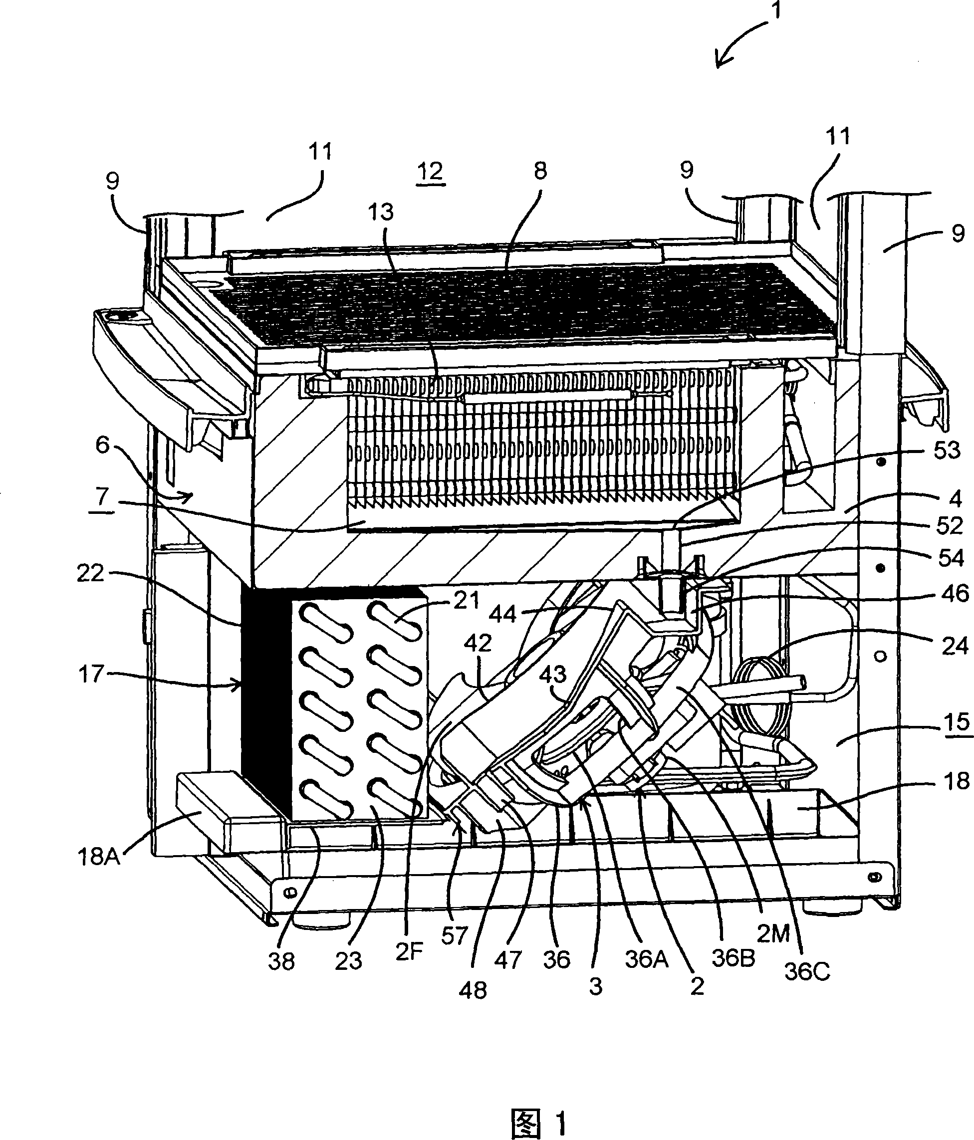
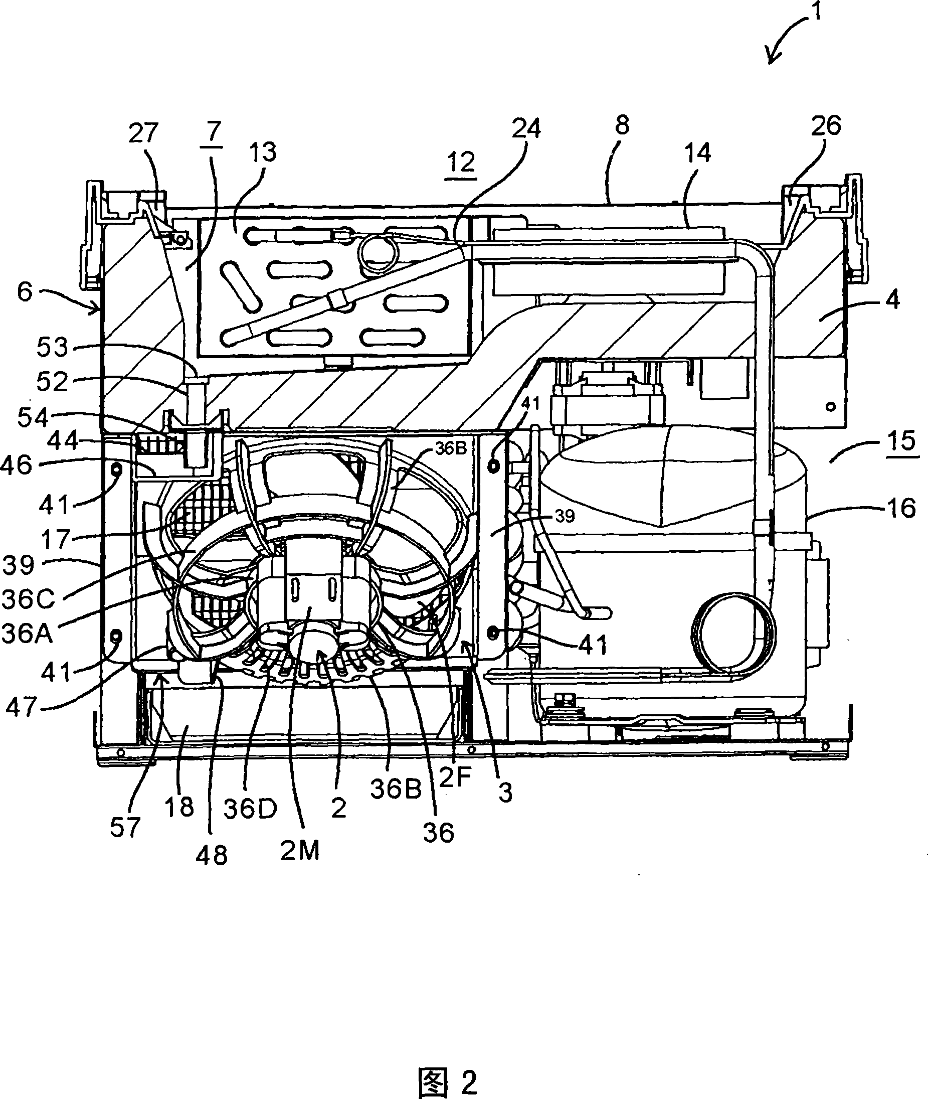
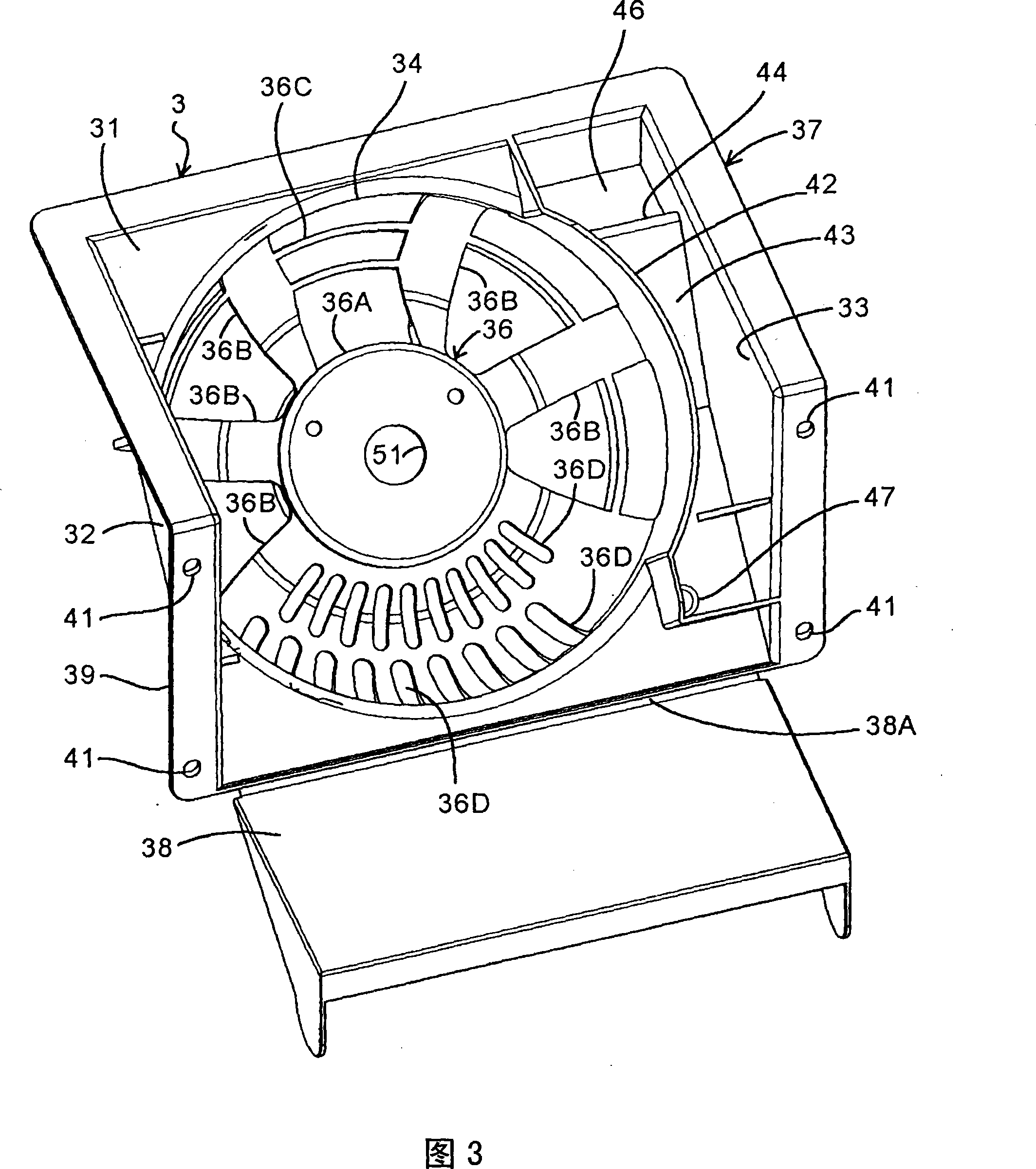
[0043] Hereinafter, embodiments of the present invention will be described in detail with reference to the drawings. Fig. 1 is a perspective perspective view of the lower part of a low-temperature showcase 1 as an embodiment of the cooling device of the present invention, Fig. 2 is a perspective rear view of the lower part of the low-temperature showcase 1, and Fig. 3 is a blower for a condenser of the low-temperature showcase 1 A perspective view of the fan cover 3 of 2.

[0044] In each figure, the low-temperature showcase 1 of the embodiment is a four-sided glass-type low-temperature showcase called a so-called desktop type, and it is provided with a rectangular container-shaped main body (showcase main body) with a heat insulating wall 4 open on the upper surface. 6. The cooling chamber 7 formed in the heat insulating wall 4 of the main body 6, the bottom plate 8 that blocks the upper surface of the cooling chamber 7, the pillars 9 erected at the four corners of the main b...


PUM


Abstract

There is disclosed a cooling device capable of simplifying attachment of a blower for a condenser and a structure of a drain path from an evaporator, and the cooling device includes a condenser (17) constituting a part of a refrigerant circuit, a condenser blower (2) which air-cools this condenser (17), and a fan casing (3) attached to the condenser (17) and provided with the condenser blower (2). The fan casing (3) is integrally provided with a bracket part (36) for attaching a motor (2M) of the condenser blower (2).

Description

technical field [0001] The present invention relates to a cooling device including a condenser of a refrigerant circuit and a condenser blower for air-cooling the condenser. Background technique [0002] Conventionally, for example, in the case of a low-temperature display cabinet, a display room is formed in the main body, cold air cooled by an evaporator in the refrigerant circuit is circulated in the display room to cool it, and a compressor, a condenser, etc. are installed in the lower part of the main body to form a display room. mechanical room. And the air blower for condensers for air-cooling a condenser is provided in the fan case (fan casing) attached to a condenser. [0003] In this case, conventionally, fan covers are installed on the tube plates on both sides of the condenser, and the blower for the condenser is installed in a grill formed by openings in the fan covers. Furthermore, the motor for driving the rotation of the air blower for condensers has a stru...

Claims


Application Information

Patent Timeline
Patent Type & Authority Applications(China)
IPC IPC(8): F25D19/00F25D21/14
CPCF25D2321/143A47F3/0482F25D2323/00281F24F2013/225F25D23/003F25D2321/1412F25D21/14F24F1/022A47F3/0443
Inventor 早濑浩二
Owner SANYO ELECTRIC CO LTD
Learn More