Light source component assembling tool and method thereof

A technology of light source components and tools, applied in optics, lighting devices, nonlinear optics, etc., can solve the problems of warping of flexible packaging tapes, uneven local force of light source components 32, and no lighting, etc., and achieve the effect of accurate assembly

Active Publication Date: 2008-08-20
KUSN INFOVISION OPTOELECTRONICS
View PDF0 Cites 1 Cited by
  • Summary
  • Abstract
  • Description
  • Claims
  • Application Information

AI Technical Summary

Problems solved by technology

Generally, taking a 14.1-inch liquid crystal display as an example, the length of the light source assembly 32 used is about 349mm, and the thickness h1 is about 1mm. The flexible packaging tape of the light source assembly 32 is easy to warp; The height h2 of the opening is about 1.1 mm, and the gap between the light source assembly 32 and the opening of the U-shaped mounting frame 31 is only about 0.1 mm.
[0006] Therefore, in the prior art, it is difficult to install the light source assembly 32 into the U-shaped installation frame 31 when manually assembling; in addition, due to the warping of the soft packaging tape of the light source assembly, it will cause The local uneven force on the light source assembly 32 causes the LED solder joints on the light source assembly to fall off, resulting in local LEDs not being bright

Method used


Image

  • Light source component assembling tool and method thereof
  • Light source component assembling tool and method thereof
  • Light source component assembling tool and method thereof

Examples


Embodiment Construction

[0038] The specific embodiment of the present invention will be described in detail below in conjunction with the accompanying drawings.

[0039] In the following description, numerous specific details are set forth in order to provide a thorough understanding of the present invention. However, the present invention can be implemented in many ways other than those described here, and those skilled in the art can make similar extensions without departing from the connotation of the present invention. Accordingly, the invention is not limited to the specific implementations disclosed below.

[0040] The schematic diagram is only a specific embodiment of the present invention, which should not limit the protection scope of the present invention.

[0041] Combine now figure 2 , image 3 , Figure 5a , Figure 5b with Image 6 The first embodiment of the present invention will be described in detail.

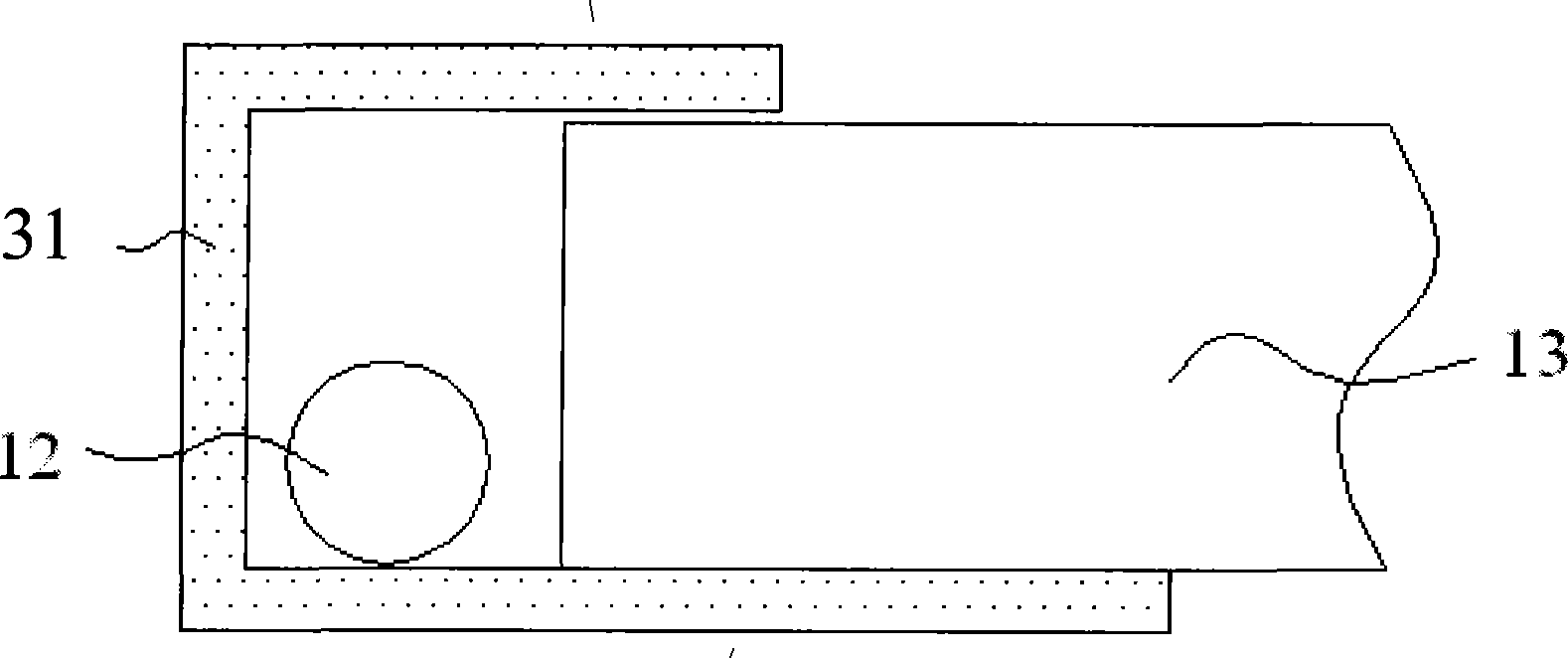
[0042] figure 2 It is a structural schematic diagram of an existing LE...


PUM

PropertyMeasurementUnit
lengthaaaaaaaaaa

Abstract

The invention discloses a assembling tool of illuminating source component and its assembling process comprising illuminating source component mounted in mounting frame which comprises clintheriform cardinal plate and fixing flat structure outspreading from side of cardinal plate. Meanwhile, the invention also discloses a method for assembling the illuminating source components applying for the assembling tool comprising: illuminating source spacing is inserted by the fixing flat structure of assembling tool, flexible encapsulation strap in the illuminating source spacing is pressed to prevent the flexible encapsulation strap from warping. The illuminating source components and assembling tools are mounted in open of mounting frame, then the assembling tool is shifted out from the mounting frame. Thereby, the problems such as the flexible encapsulation strap warping and illuminating source welding spot falling-off on illuminating source component of LCD device are solved and assembling becomes more accurate and more labor-saving.

Description

technical field [0001] The invention relates to the field of liquid crystal display devices, in particular to an assembly tool and an assembly method for assembling a light source component of a liquid crystal display device. Background technique [0002] In recent years, liquid crystal displays have been widely used in various fields due to their lightness, thinness and high resolution. Liquid crystal displays can be divided into reflective liquid crystal displays, transmissive liquid crystal displays, and transflective liquid crystal displays according to their light source utilization forms. Taking the transmissive or transflective liquid crystal display as an example, it is mainly composed of a liquid crystal panel and a backlight module. The liquid crystal panel is composed of two transparent substrates and a liquid crystal arranged between the two transparent substrates. layer, and the backlight module is used to provide the light source required by the liquid crystal...

Claims


Application Information

Patent Timeline
Patent Type & Authority Applications(China)
IPC IPC(8): G02F1/13357G02F1/1333F21V21/00G02F1/1335
Inventor 曲艳玲陈世宪党鹏乐赖信杰
Owner KUSN INFOVISION OPTOELECTRONICS
Why Eureka
Try Eureka