Generation method of dynamic independent collimating device collimation block movement path

A technology of motion trajectory and collimator, applied in the direction of using diaphragm/collimator, X-ray/γ-ray/particle irradiation therapy, etc., can solve the problem of long static intensity modulation treatment time, long treatment time, Problems such as low utilization rate of rays

Inactive Publication Date: 2008-08-20
CANCER INST & HOSPITAL CHINESE ACADEMY OF MEDICAL SCI
View PDF1 Cites 11 Cited by
  • Summary
  • Abstract
  • Description
  • Claims
  • Application Information

AI Technical Summary

Problems solved by technology

The disadvantage of independent collimator intensity modulation is that the treatment time is longer and the utilization rate of rays is lower
[0009] In order to solve the shortcomings of the in

Method used


Image

  • Generation method of dynamic independent collimating device collimation block movement path
  • Generation method of dynamic independent collimating device collimation block movement path
  • Generation method of dynamic independent collimating device collimation block movement path

Examples


Embodiment Construction

[0049] Refer below Figure 7 The method for generating the motion trajectory of the collimation block of the dynamic independent collimator according to the first embodiment of the present invention is described.

[0050] First, step (1): determine the ideal intensity distribution.

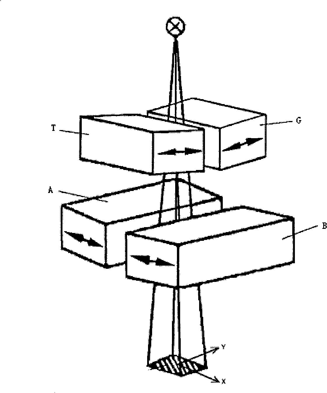
[0051] (2) Use a real number variable to represent the position of the collimation block of the independent collimator at each control point, where the positions of the collimation block A, the collimation block B, the collimation block G, and the collimation block T when the cumulative irradiation time is t The positions respectively denote J A (t), J B (t), J G (t), J T (t).

[0052] (3) Based on the positions of the four collimation blocks, calculate the intensity distribution I(x, y) of any point (x, y) in the field of view according to formula (1):

[0053] I ( x , y ) = ∫ ...


PUM


Abstract

The invention relates to a method for optimal generation of a independent collimator collimation block trajectory according to a specific intensity distribution, comprising the steps of: representing the independent collimator collimation block position of each control point by a real variant, calculating the intensity distribution of any point in the radiation field according to the dynamic trajectory of the, deciding the motion constraint conditions of the collimation block, creating a objective function, performing optimization, and generating the independent collimator collimation block trajectory. By the collimation block trajectory generating method using dynamic independent collimator, the conformity between the real intensity distribution and the ideal intensity distribution is better than that of static intensity modulation, the modulation time can be greatly reduced, and the execution efficiency is improved.

Description

technical field [0001] The invention relates to a method for generating a motion track of a collimation block of a dynamic independent collimator according to a specific or arbitrary intensity distribution. Background technique [0002] At present, the more commonly used technology is to apply collimator for intensity modulation, including multileaf collimator (multileaf collimator, MLC) and independent collimator (independent collimator, IC), both of which limit the irradiation range of the ray beam. device. The former is composed of two sets of oppositely arranged blades, and irregular shooting fields with stepped edges can be formed through the independent movement of each blade. The latter consists of two pairs of four collimating blocks. By moving the two pairs of collimating blocks along the directions perpendicular to each other, rectangular irradiation fields of different sizes can be formed. [0003] MLC intensity modulation is a kind of intensity modulation meth...

Claims


Application Information

Patent Timeline
IPC IPC(8): G21K1/04A61N5/10
Inventor 戴建荣张永谦
Owner CANCER INST & HOSPITAL CHINESE ACADEMY OF MEDICAL SCI
Why Eureka
Try Eureka