
Substrate support assembly

A technology for components and supporting substrates, which can be used in electrical components, semiconductor/solid-state device manufacturing, crystal growth, etc., to solve the problems of burn-in connector glow discharge or micro-arcing, damage, and increase the cost of unit substrate preparation.

Inactive Publication Date: 2008-08-20
APPLIED MATERIALS INC
View PDF2 Cites 6 Cited by
  • Summary
  • Abstract
  • Description
  • Claims
  • Application Information

AI Technical Summary

Problems solved by technology

The RF potential applied to the electrodes used to excite the gas in the chamber can also cause glow discharges or micro-arcing that damage or "burn" the connectors and adjacent parts of the stent
In some plasma environments, after processing only a relatively small number of substrates, the degradation of the substrate support assembly and its conductor assembly may require their retooling or replacement, which increases the preparation cost per substrate

Method used


Image

  • Substrate support assembly
  • Substrate support assembly
  • Substrate support assembly

Examples


Embodiment Construction

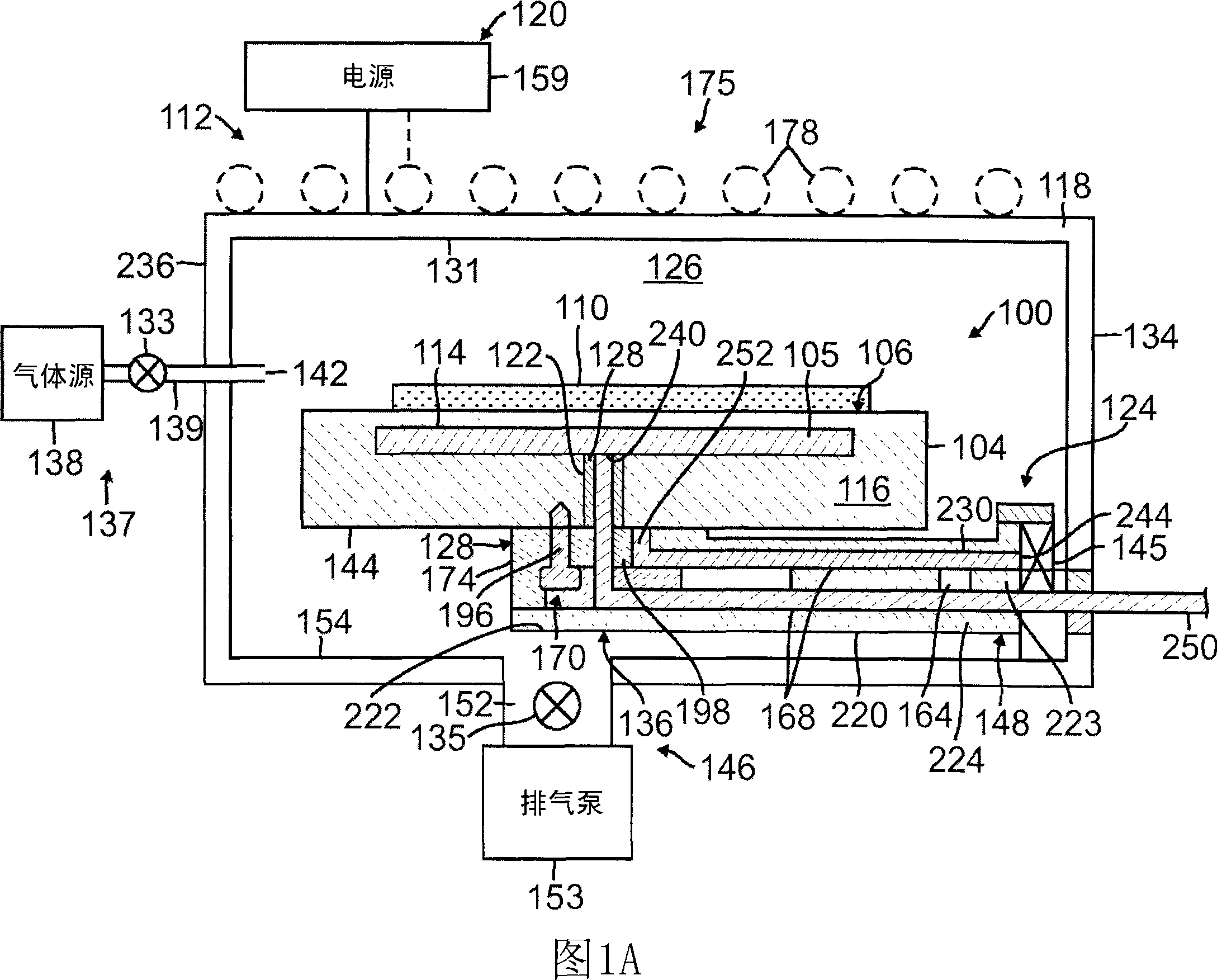
[0017] As shown in FIG. 1A , the substrate support assembly 100 includes a support block 104 having a substrate receiving surface 106 for supporting a substrate 110 in a processing chamber 112 . In the form shown, the standoff block 104 includes a dielectric block 116 made of, for example, aluminum nitride, aluminum oxide, or silicon oxide. Dielectric block 116 may be a monolithic or unitary structure of dielectric material (as shown), or may be made from multiple stacked plates of dielectric material. While one form of substrate support assembly 100 is shown here, it should be understood that other forms are within the scope of the present invention as will be apparent to those skilled in the art. For example, support block 104 may also be a metal block constructed of aluminum or stainless steel with a corrosion resistant coating such as anodized aluminum disposed on substrate receiving surface 106 .

[0018] The support block 104 includes an electrode 114 adapted to be part...


PUM


Abstract

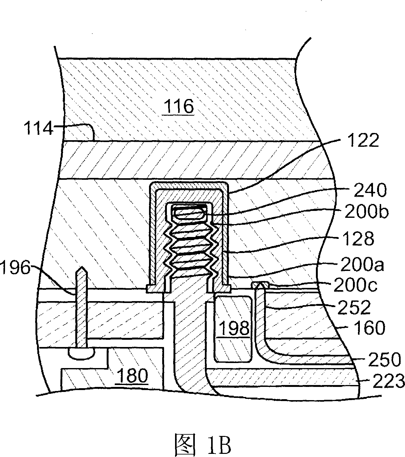
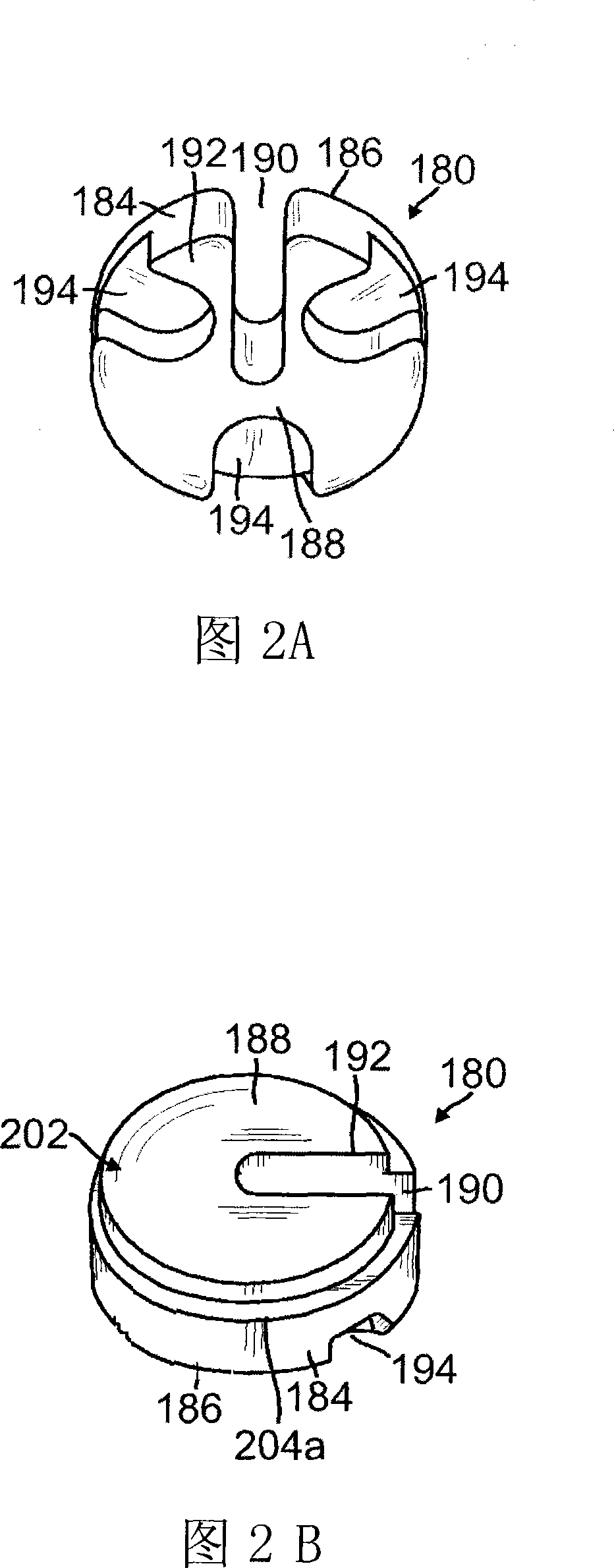
A substrate support assembly comprises a support block having an electrode and an arm to hold the support block in the process chamber, the arm having a channel therethrough. The arm has a first clamp to attach to the support block and a second clamp to attach to a chamber component. A cover lock comprises an annular disc that is seated in the arm beneath the first clamp to cover and seal off electrical conductors in the channel from the chamber environment.

Description

technical field [0001] Embodiments of the invention relate to a substrate support assembly for supporting a substrate in a processing chamber. Background technique [0002] In the fabrication of electronic circuits such as, for example, integrated circuits and displays, a substrate is placed in a process chamber and a process gas is introduced into the chamber to process the substrate. A processing chamber generally includes an enclosure wall surrounding a substrate processing area. Gas energizers can be used to excite process gases by applying RF or microwave energy to the gas. The process gas is excited to etch features in layers on the substrate or to deposit layers on the substrate. [0003] In the processing chamber, the substrate is held on the substrate receiving surface of the substrate holder. The substrate holder may have electrodes that can be charged to electrostatically hold the substrate. The electrode can also be charged or held at ground potential by an e...

Claims


Application Information

Patent Timeline
IPC IPC(8): H01L21/683H01L21/00C23F4/00C23C16/458C23C16/44C23C14/50C30B25/12
CPCH01L21/6831H01L21/687
Inventor 克里斯多佛·理查德·马洪阿布海杰特·德塞罗伯特·T·海拉哈拉
Owner APPLIED MATERIALS INC
Learn More