Eureka AIR delivers breakthrough ideas for toughest innovation challenges, trusted by R&D personnel around the world.

Control of an electrical machine

A technology of switched reluctance motor and operating mode, which is applied in control system, AC motor control, single motor speed/torque control, etc. It can solve the problem of not considering progress and achieve the effect of reducing switching frequency

Inactive Publication Date: 2013-01-02
NIDEC SR DRIVES
View PDF2 Cites 0 Cited by
  • Summary
  • Abstract
  • Description
  • Claims
  • Application Information

AI Technical Summary

Problems solved by technology

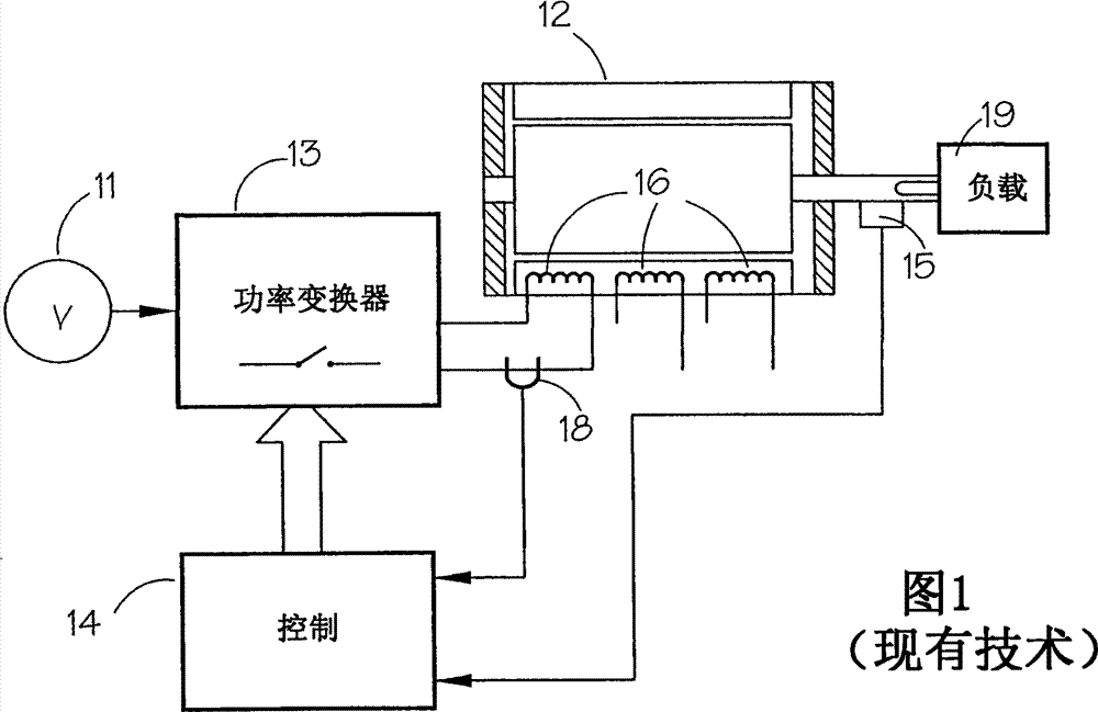
[0015] The prior art does not contemplate advances in this manner of operating a motor without changing the order in which phases are energized during motor operation

Method used


Image

  • Control of an electrical machine
  • Control of an electrical machine
  • Control of an electrical machine

Examples


Embodiment Construction

[0052] Fig. 6 shows the rectangular waveform of the sensor output of Fig. 4(b) superimposed with the triangular phase flux waveform. Pick an arbitrary point as the operating point of the system for interpreting the sensor waveform (e.g., typically L min ) on the rising edge of the switch is turned on and the switch is turned off a quarter of a cycle later. The purpose here is to explain. The operating point at which the switch is turned on to start energization and drives the flux up and the switch is turned off to drive the flux down varies. The phases of the motor are energized in a predetermined sequence ABC.

[0053] Figure 7 shows one embodiment graphically. The motor still runs at the same speed as in Figure 6. The speed at which the rotor poles pass the stator poles is thus the same. Therefore, the period of the sensor waveform is the same. However, each phase is now energized at a lower rate, in this case half the original rate. When the rotor poles reach the ph...


PUM


Abstract

A switched reluctance machine has salient poles on the stator and rotor. The windings of the machine are supplied from a converter which provides energisation at a chosen rate. The windings of the machine may be energised at the rate at which the rotor poles pass the stator poles, or it may be operated at a fraction of that rate by energising the windings to cooperate with every second, third or fourth rotor pole. This can extend the output of the machine.

Description

technical field [0001] The present invention generally relates to methods of controlling electric motors. More particularly, but not exclusively, the present invention relates to the operation of a switched reluctance motor. Background technique [0002] One form of switched reluctance motor has a single field, doubly salient electromagnetic structure, which is generally not made of hard magnetic materials. The presence of rotor position detectors and the application of an energization (commonly referred to as "excitation") strategy results in these machines having what is generally described as "switched rotor position", where the energization strategy is entirely dependent on the instantaneous position of the rotor. A general treatment of variable speed drives including these motors can be found in various textbooks, for example, "Electronic Control of Switched Reluctance Machines" by TJE Miller, Newnes, 2001, incorporated herein by reference. Further characteristics and...

Claims


Application Information

Patent Timeline
Patent Type & Authority Patents(China)
IPC IPC(8): H02P6/08H02P25/08
CPCH02P25/085H02P25/088H02P25/092H02P25/098H02P25/08
Inventor S·P·兰德尔
Owner NIDEC SR DRIVES
Why Eureka
Eureka Blog
Learn More