
Information terminal device

a technology of information terminals and terminals, which is applied in the direction of television systems, instruments, stoves or ranges, etc., can solve the problems of mechanical difficulties, and the arrangement of providing image pickup sections with a specific distance has not been realized in any size of devices

Inactive Publication Date: 2008-07-08
SHARP KK
View PDF28 Cites 24 Cited by
  • Summary
  • Abstract
  • Description
  • Claims
  • Application Information

AI Technical Summary

Benefits of technology

[0012]An object of the present invention is to provide a folding information terminal device capable of taking and displaying a superior three-dimensional image than that taken by a conventional folding information terminal device. The object is achieved with a folding information terminal device for taking a three-dimensional image, in which the respective image pickup sections for capturing a three-dimensional image are provided with a longer interval than a conventional folding information terminal device for taking a three-dimensional image.
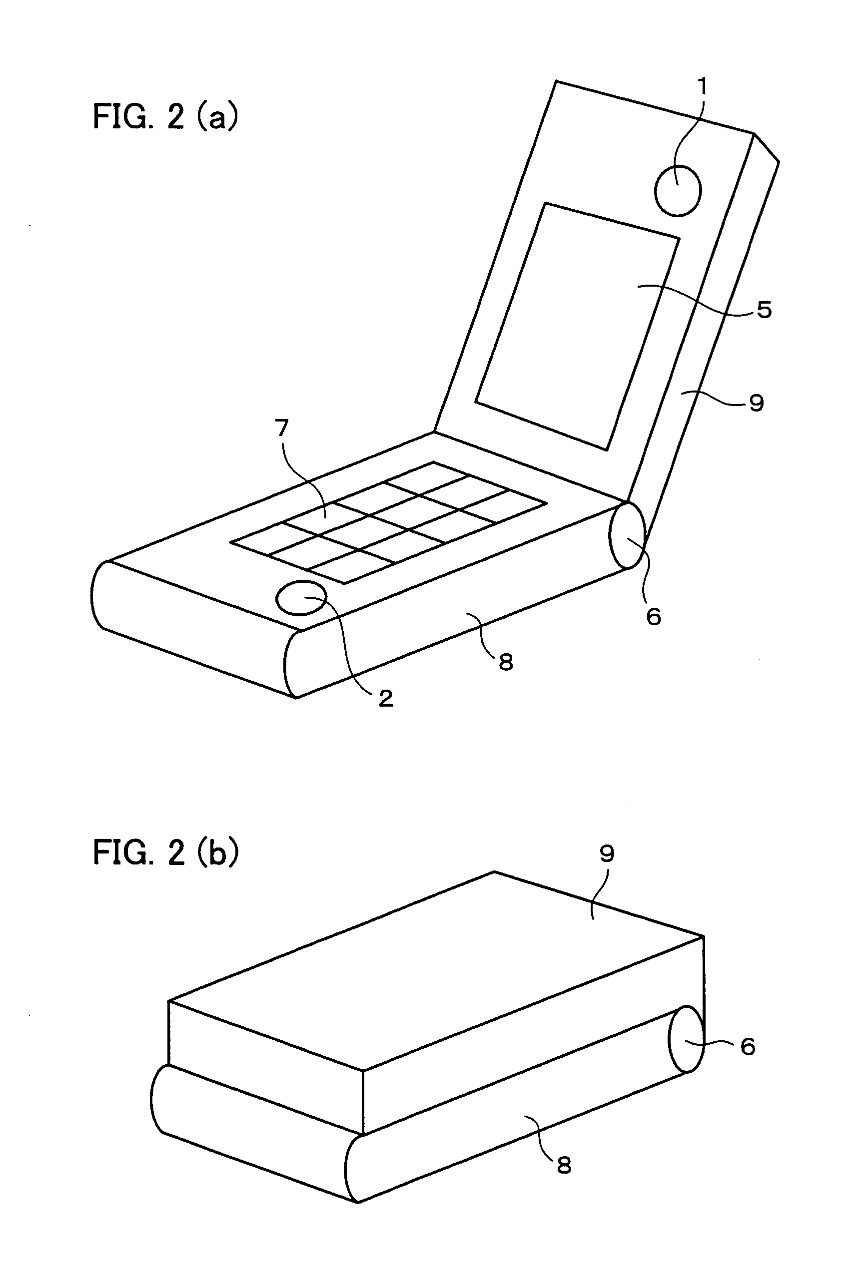
[0014]With the foregoing arrangement, the folding information terminal device, which has two planes, includes a plurality of image pickup sections, as at least one image pickup section is provided on one plane, and at least one image pickup section is provided on the other plane. Therefore, the information terminal device is capable of simultaneously taking the same object with a plurality of image pickup sections at different positions. More specifically, a plurality pieces of image data with parallax regarding the same object can be captured to the information terminal device, thus enabling the information terminal device to take a three-dimensional image.
[0015]Further, the information terminal device includes at least one image pickup section on one plane of the two planes and at least one image pickup section on the other plane of the two planes, which become opposite to each other when the folding information terminal device is folded. With such a structure, the interval between the respective image pickup sections can be extended, compared to the conventional structure in which the image pickup sections are provided only on the display section (only on one plane), thus capturing a plurality pieces of image data with larger parallax than that of a conventional information terminal device. On this account, it is possible to capture a superior three-dimensional image than that captured by a conventional device.

Problems solved by technology

However, in case of adopting such a folding information terminal device for a small-sized device such as a mobile phone, there arise some mechanical difficulties to place the image pickup sections 104 and 105 in the display section 101, while providing a specific distance between them.
Further, for a conventional folding information terminal device, the arrangement of providing image pickup sections with a specific distance has not been realized in any sizes of device.

Method used


Image

  • Information terminal device
  • Information terminal device
  • Information terminal device

Examples


first embodiment

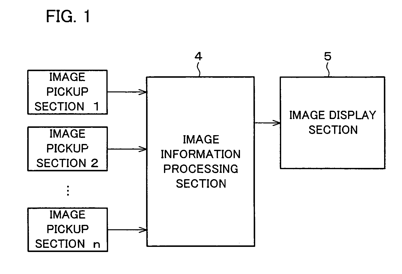
[0034]One embodiment of the present invention will be described below with reference to Figures. FIG. 1 is a block diagram illustrating a three-dimensional image display system included in an information terminal device according to the present embodiment.

[0035]As shown in FIG. 1, the information terminal device includes a plurality of image pickup sections 1 through n. The image pickup sections are each made of a CCD camera or a CMOS image sensor. Note that, at least one of the image pickup sections is required for each of a covering body and a main body of the information terminal device (i.e., at least two in total).

[0036]An image information processing section 4 is a block for converting the image data, which has been taken by the image pickup sections 1 through n, into image data compatible with the display mode of an image display section 5.

[0037]Note that, when the information terminal device has two image pickup sections, the image information processing section 4 outputs im...

second embodiment

[0053]Another embodiment of the present invention will be described below with reference to figures. FIG. 3 is a perspective view illustrating the outer shape of an information terminal device according to the present embodiment. FIG. 4 shows a side view of the information terminal device. This information terminal device according to the present embodiment includes the image pickup section 1 and the image pickup section 2, which are provided so that the distance d1 between the image pickup section 1 and the movable connection section 6, and the distance d2 between the image pickup section 2 and the movable connection section 6 are identical. With this structure, as shown in FIG. 4, the user can set the intersection of the shooting direction of the image pickup section 1 and the shooting direction of the image pickup section 2 to be placed on the center of the front side of the information terminal device and the user, by holding the information terminal device with the surface of t...

third embodiment

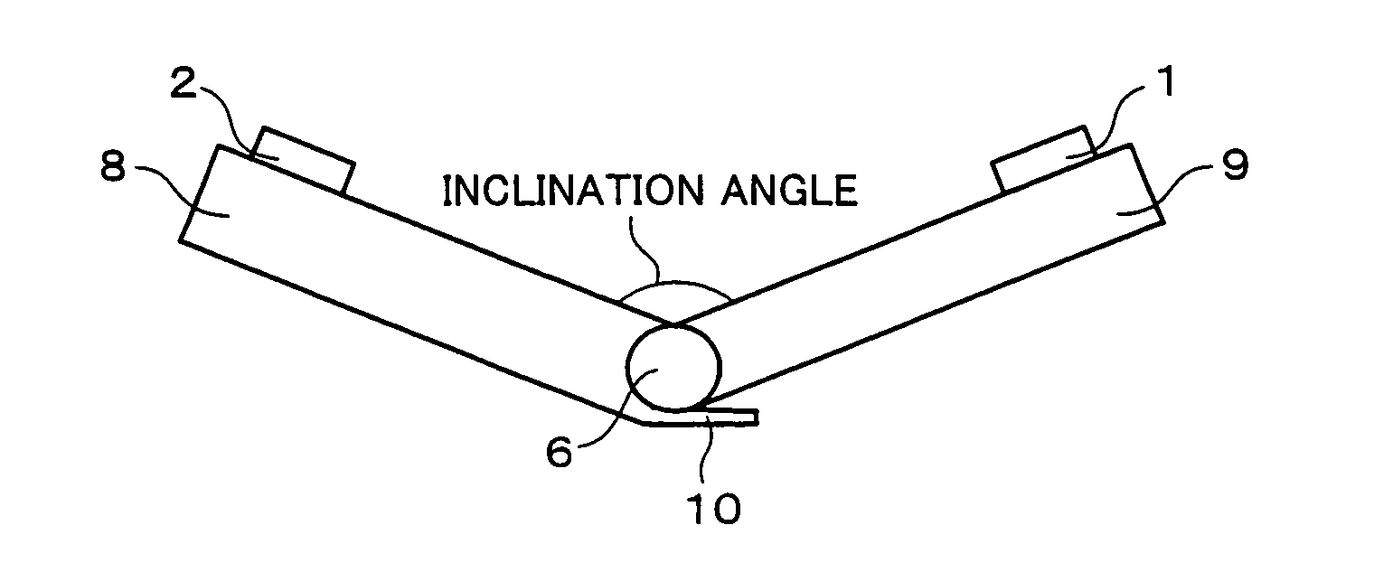
[0055]Still another embodiment of the present invention will be described below with reference to figures. FIG. 5 is a side view illustrating the outer shape of an information terminal device according to the present embodiment. In addition to the arrangement described in First Embodiment and Second Embodiment, the information terminal device of the present embodiment further includes a movable range restriction section 10 on the main body 8. The movable range restriction section 10 is protruded from the rear surface of the main body 8. The movable range restriction section 10 is brought into contact with the rear surface of the covering body 9 when the inclination of the covering body 9 with respect to the main body 8 becomes a predetermined angle, so as to prevent the inclination of the covering body 9 with respect to the main body 8 from exceeding the predetermined angle (so as to stop the movable connection section 6 before exceeding the predetermined angle).

[0056]Incidentally, ...


PUM


Abstract

In a folding information terminal device capable of taking a three-dimensional image and including two planes which become opposite to each other when the folding information terminal device is folded; there is provided at least one image pickup section on one plane of the two planes, and at least one image pickup section on the other plane.

Description

[0001]This Nonprovisional application claims priority under 35 U.S.C. § 119(a) on Patent Application No. 2003 / 008815 filed in Japan on Jan. 16, 2003, the entire contents of which are hereby incorporated by reference.FIELD OF THE INVENTION[0002]The present invention relates to an information terminal device capable of taking and displaying a three-dimensional image.BACKGROUND OF THE INVENTION[0003]Conventionally, a three-dimensional image display device for displaying a three-dimensional image has been used for various purposes, such as computer games, CAD systems, airplanes, and medical devices etc. The following explains a typical principle for providing a user with a three-dimensional image.[0004]Display of a three-dimensional image is carried out by capturing an image at plural different angles, and then displaying the plurality of captured images with parallax with respect to both eyes of the user. Accordingly, when capturing image data for performing three-dimensional image dis...

Claims


Application Information

Patent Timeline
IPC IPC(8): H04N5/225H04M1/00G06F1/16H04N13/243H04M1/02H04N13/239
CPCH04M1/021H04M1/0214H04M1/0243H04N13/0296H04N13/0239H04N13/0246H04N13/0285H04M1/0264H04N13/0257H04M2250/20H04N13/246H04N13/257H04N13/296H04N13/286H04N13/239H04N13/243F24C15/023F24C3/008
Inventor EZAWA, MASAYUKI
Owner SHARP KK
Learn More