Refuse/oil removing device and refuse/oil recovery bag

a technology of refuse/oil recovery bag and recovery bag, which is applied in the direction of sedimentation settling tank, liquid displacement, separation process, etc., can solve the problems of inconvenience, oxidization and rot, and emit an offensive smell, so as to improve the rate of settling down full-time, reduce the amount of oil accumulated in the second tank of the grease trap, and reduce the amount of oil accumulated in the second tank. , the effect of reducing the amount of oil

Inactive Publication Date: 2010-10-19
KOMATSU KIYOSHI
View PDF30 Cites 25 Cited by
  • Summary
  • Abstract
  • Description
  • Claims
  • Application Information

AI Technical Summary

Benefits of technology

[0014]The present invention has been accomplished in view of the above-mentioned problems and provides a refuse / oil removing device able to remove refuse and oil contained in drainage from restaurants without contact with the refuse and oil and that in a simple manner, as well as a recovery bag for the recovery of such refuse and oil.
[0019]According to the present invention, by merely taking out the recovery bag from the support means, it is possible to remove refuse and a large amount of oil which, without the recovery bag, would be discharged into the grease trap. The work required is as simple as merely replacing the recovery bag. The work of removing refuse from residue and the work of cleaning a residue basket, which have so far been required, can be omitted. As a result, unpleasant works associated with the grease trap are no longer needed and hence it is possible to improve the rate of settling down of full-time and part-time workers in restaurants. Moreover, the bag portions of the recovery bag are always positioned above the water level in the grease trap and therefore, if the recovery bag is removed when there is no water within the bag portions, there no longer is any drop of water from the recovery bag nor is the hand stained with drainage. In the present invention, the movable member for attaching and detaching the recovery bag in the support means is movable relative to the leg portions and other portions, and by moving only the movable member without moving the whole of the support member, the recovery bag can be attached to and detached from the drain pipe and thus the recovery bag attaching and detaching work becomes very easy.
[0020]In the present invention, the bag portions of the recovery bag are formed as plural layers and are formed of a material which permits the adhesion of oil thereto. Thus, refuse and oil can be trapped by the plural layers of bag portions and most of oil discharged from discharge means toward the grease trap, as well as refuse adhered to the oil, can be trapped. As a result, not only the amount of oil accumulated in the second tank of the grease trap can be greatly diminished and the interval of the work for removing oil from the second tank can be greatly prolonged, but also the interval of cleaning within the grease trap can be prolonged and the cost of the cleaning work can be greatly decreased.

Problems solved by technology

If food residue is kept immersed in water and a long time elapses, they oxidize and rot, emitting an offensive smell.
If the full-time and part-time workers are compelled to participate in such jobs, many of them leave the restaurants on the ground that they dislike those jobs.
Therefore, an inconvenience has so far occurred, such that both full-time and part-time workers must be invited hired constantly.
If the workers fail to perform the food residue removing work and the cleaning work for the residue basket 26, rot proceeds and the rotten smell becomes more offensive.
To avoid this, busy managers are compelled to do those jobs, that is, the burden on the managers increases.

Method used


Image

  • Refuse/oil removing device and refuse/oil recovery bag
  • Refuse/oil removing device and refuse/oil recovery bag
  • Refuse/oil removing device and refuse/oil recovery bag

Examples


Embodiment Construction

[0031]The present invention will be described hereinunder with reference to the drawings.

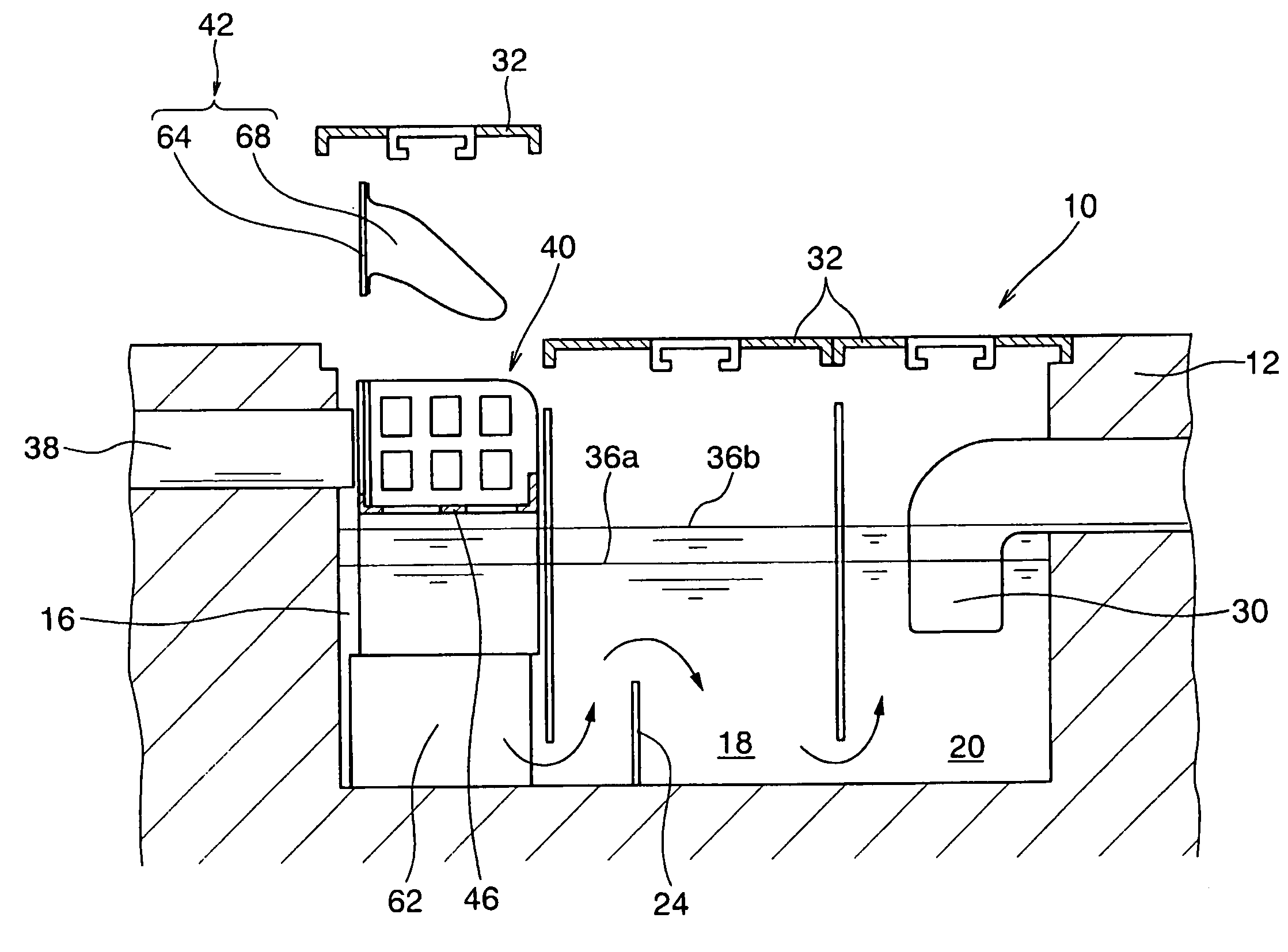
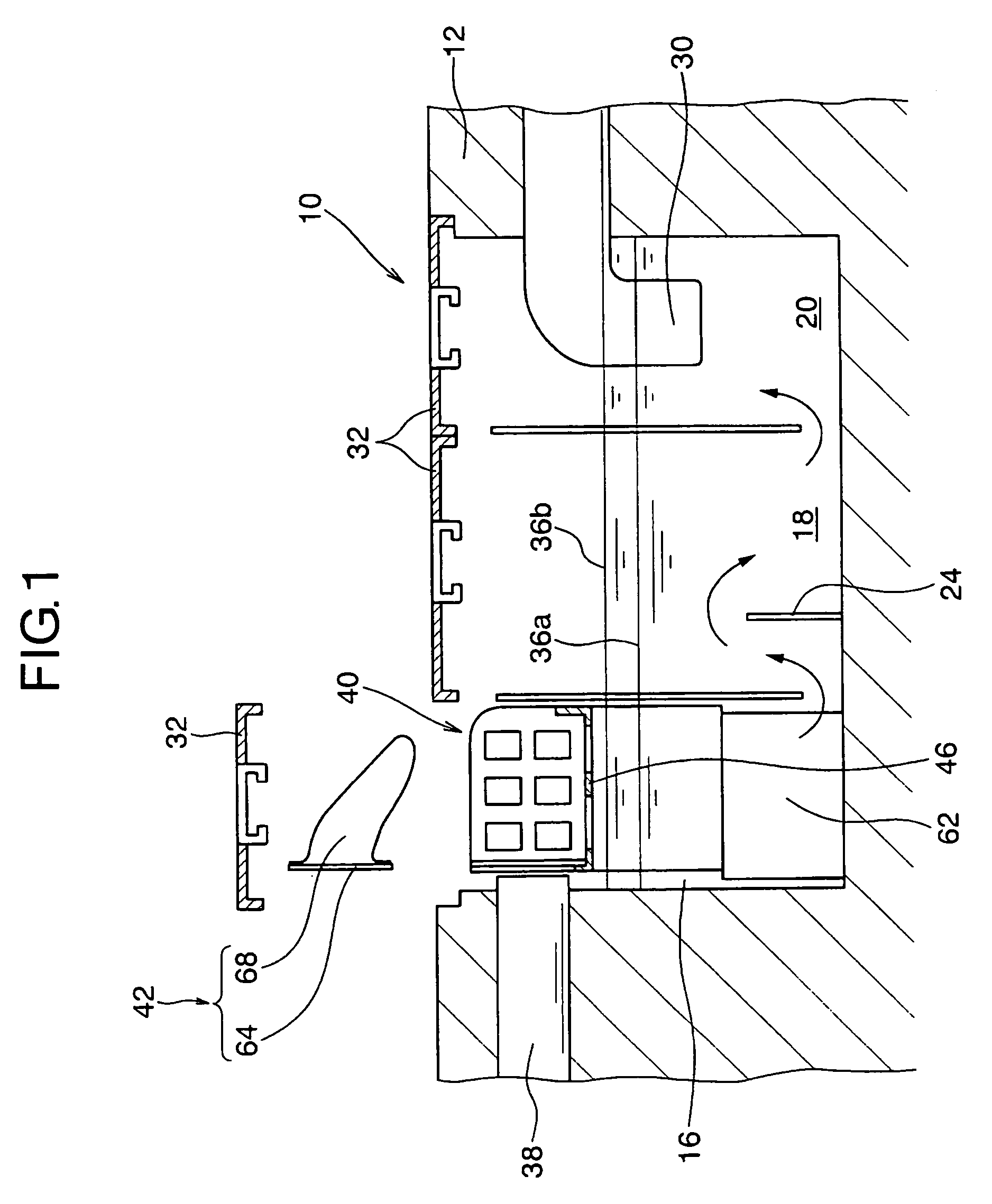
[0032]FIG. 1 is a sectional view showing a state in which a refuse / oil removing device according to the present invention is provided within a grease trap, FIG. 2 is a perspective view showing an example of a support means used in the present invention, and FIG. 3 is a perspective view showing an example of a recovery bag used in the present invention. In FIG. 1, the same reference numerals as in FIG. 10 represent the same members as in FIG. 10. In the present invention there is used a conventional, known grease trap 10, provided it is preferable that an outlet side of an upstream drain passage for introducing drainage into a first tank 16 be not a gutter but a drain pipe 38. In the refuse / oil removing device according to the present invention, support means 40 shown in FIG. 2 and a recovery bag 42 shown in FIG. 3 are used instead of the residue basket 26 shown in FIG. 10.

[0033]The support means...


PUM

PropertyMeasurementUnit
sizeaaaaaaaaaa
diameteraaaaaaaaaa
diameteraaaaaaaaaa

Abstract

A refuse / oil removing device and a refuse / oil recovery bag are provided which can remove refuse and oil contained in drainage discharged from a restaurant in a simple manner without contact with the refuse and oil. A support base of a support unit is disposed in the interior of a grease trap at a position higher than the water level. A recovery bag is attached to the support unit and plural layers of bag portions of the recovery bag are put on the support base. The bag portions are each formed of a material which permits the adhesion of oil thereto and a large number of water passing holes are formed in each of the bag portions. Drainage is introduced inside the innermost one of the plural layers of bag portions and is passed through the bag portions, allowing refuse and oil to adhere to the bag portions. In this way, the job of replacing the recovery bag can be simplified and the amount of oil accumulated within the grease trap can be decreased.

Description

BACKGROUND OF THE INVENTION[0001]I. Technical Field[0002]The present invention relates to a refuse / oil removing device for removing refuse and oil contained in drainage from restaurants, as well as a recovery bag for the recovery of such refuse and oil.[0003]II. Description of Related Art[0004]A large amount of refuse having shapes (e.g., food residues, toothpicks and skewers) and oil (sludge such as oil and fat) are mixed in drainage discharged from kitchens for business use such as those in restaurants wherein cooking and washing of tableware are performed frequently. When such refuse and oil flow through a sewer pipe, they adhere to the inner surface of the pipe and coagulate, with a likely consequence that the pipe diameter may be reduced or the pipe may be blocked. There also has been the problem that the environment, including rivers, is badly influenced by outflow of such refuse and oil into a public sewerage.[0005]For preventing the occurrence of the above problem, in restau...

Claims


Application Information

Patent Timeline
Patent Type & Authority Patents(United States)
IPC IPC(8): B01D36/04B01D29/27B01D17/00B01D21/00C02F1/40E03F5/16
CPCB01D17/00B01D21/0003B01D21/0012B01D21/003B01D21/0042B01D21/0066B01D21/02B01D21/2405B01D21/2483E03F5/16B01D17/0211B01D17/0214B01D17/08B01D21/0039B01D2221/02C02F1/40
Inventor KOMATSU, KIYOSHI
Owner KOMATSU KIYOSHI
Why Eureka
Try Eureka