Electric oil injector

An electronic fuel injection and nozzle technology, which is applied in the direction of fuel injection devices, charging systems, engine components, etc., can solve the problems of poor injection randomness and stability, poor hot start and stability, and large influence of fuel vapor, so as to improve injection The effect of stability, low cost and simple structure

Inactive Publication Date: 2010-09-01
塞尔福(厦门)工业有限公司
View PDF6 Cites 0 Cited by
  • Summary
  • Abstract
  • Description
  • Claims
  • Application Information

AI Technical Summary

Problems solved by technology

However, when the engine is in a hot car state, especially when the engine is in a hot car start state, and the intake pressure fluctuates greatly, fuel vapor has a great influence on the normal operation of the fuel injection device. Therefore, how to design such a fuel injection device to facilitate hot car start is a problem. problem
In addition, in the prior art, the multi-hole nozzle is widely used in the oil supply system of the piston engine, and its biggest disadvantages are: high manufacturing cost and poor injection stability
However, since the fuel chamber has steam, it can only bring fresh fuel into the pressure chamber through the suction overflow passage, so when the engine is running at high load for a long time, especially in the climbing state with poor cooling conditions, then the heat If the car is left alone, it cannot be started, that is, its hot start and stability are extremely poor at high temperatures
In addition, because the injection volume of the nozzle is directly related to the actual open flow area between the valve body and the valve seat, the randomness and stability of the injection are extremely poor.

Method used


Image

  • Electric oil injector
  • Electric oil injector
  • Electric oil injector

Examples


Embodiment 1

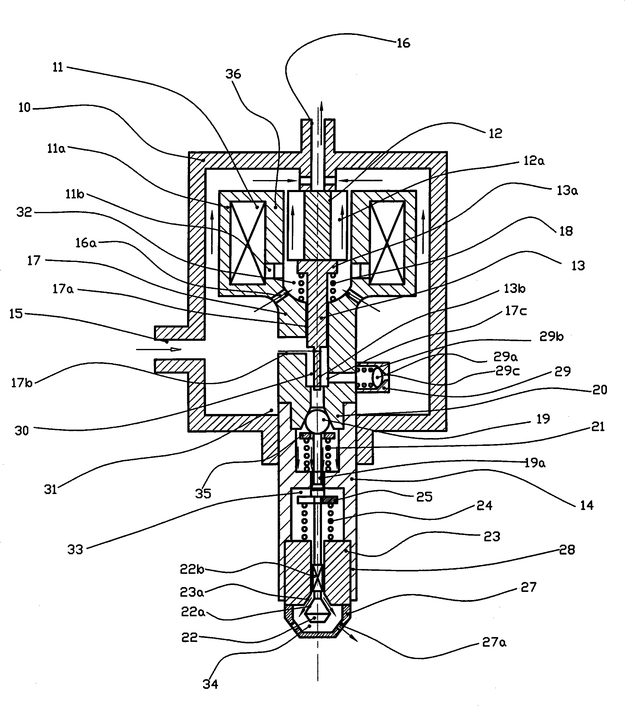
[0024] Embodiment 1: as figure 1 As shown, the electronic fuel injection device of the present invention includes: an oil casing 10, a coil 11, an approximately cylindrical armature 12, an approximately cylindrical plunger 13, a nozzle 14, an oil inlet 15, an Oil return port 16, a sleeve 17 that approximates a round hole.

[0025] The plunger 13 fits precisely with the inner hole 17a of the sleeve 17 and can move freely therein. The space formed by the lower end of the plunger 13 and the inner wall of the sleeve 17 is a pressure chamber 30, and the space between the oil casing 10, the coil 11 and the outer wall of the sleeve 17 A fuel chamber 31 is formed.

[0026] The side wall of the sleeve 17 is provided with a suction overflow hole 17b and an oil inlet valve hole 17c, and its lower end is provided with an oil outlet valve 35 composed of an oil outlet valve core 19, an oil outlet valve seat 20 and an oil outlet valve spring 21. The suction overflow hole 17b is located at ...

Embodiment 2

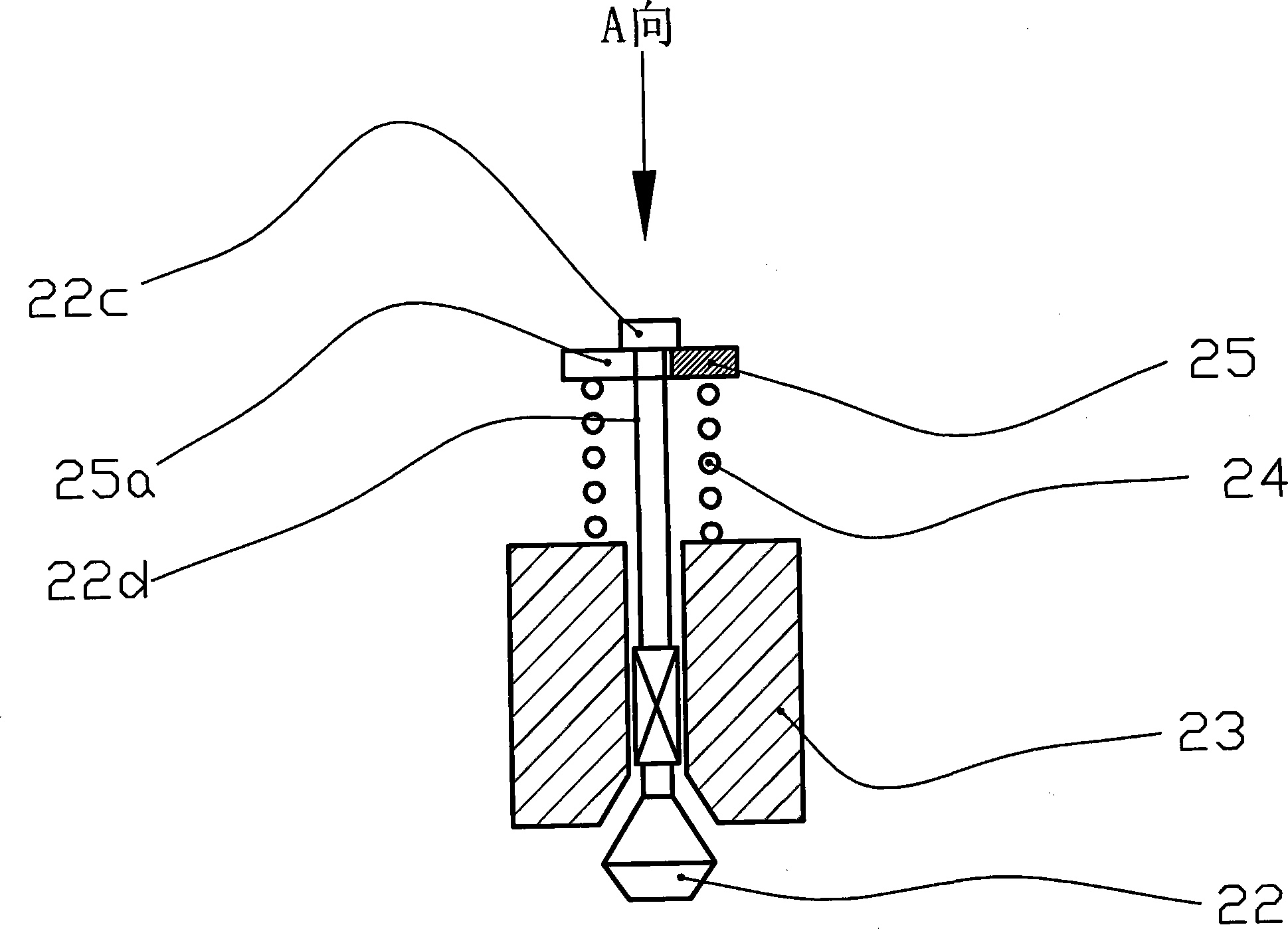
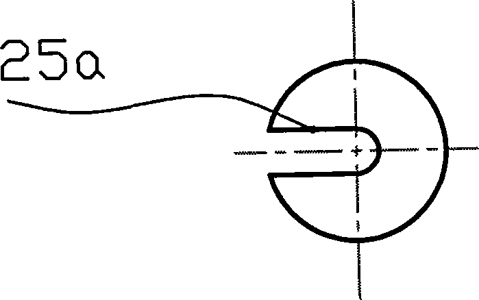
[0045] Embodiment 2: as Figure 4 , Figure 5 In the shown nozzle valve, the structure difference from Embodiment 1 is: the tail of the nozzle valve body 22 has a boss 22c that is approximately cuboid and a thin rod 22d; the center of the spring seat 25 of the nozzle valve has a shape similar to the boss 22c. The rectangular middle hole 25b; the boss 22c can pass through the rectangular middle hole 25b smoothly, and after being rotated at an angle, it is pressed against the nozzle valve body 22 under the pressure of the nozzle valve spring 24 .

Embodiment 3

[0046] Embodiment 3: as Figure 6 In the nozzle valve shown, the structure difference from Embodiment 1 is: there is a thin rod 22d at the end of the nozzle valve body 22, and there is a central hole 25c in the center of the nozzle valve spring seat 25, which is similar in shape to the thin rod, and the thin rod 22d penetrates the central hole In 25c, the end faces of the two are approximately flush, and welding is performed at the seams of the two.


PUM


Abstract

The invention provides an electronic fuel oil injection device, comprising a fuel housing, wherein, the fuel housing is provided with an inlet opening and a return opening, the inner part of the fuel housing is provided with a combustion chamber, a plunger piston and a sleeve which are in sliding fit with each other, and an electromagnetic powerplant for driving the plunger piston, the lower end of the plunger piston and the sleeve form a pressure chamber, the lower part of the pressure chamber is provided with a fuel oil outlet valve and a nozzle in sequence, the side wall of the sleeve is provided with a fuel spill absorbing hole and a fuel oil inlet valve hole, the fuel spill absorbing hole is positioned at the upper end of the pressure chamber, the fuel oil inlet valve hole is positioned at the lower end of the pressure chamber, and the fuel oil inlet valve hole is provided with a fuel oil inlet valve. The electronic fuel oil injection device has the advantages that the structure is simple, the number of elements is small, the cost is low, the possibility of the generation of the fuel steam is greatly reduced, the fuel steam can be discharged effectively, the normal operation of the injection device is quickly recovered, and the warm start performance at a high temperature is greatly improved. In addition, the emitted dose of the nozzle is not directly related with the practically opened circulation area between the valve body and the valve seat but with the sum of all the nozzle hole areas; the injection stability of the nozzle is greatly improved compared with the circumstance of no nozzle cap limitation.

Description

technical field [0001] The invention belongs to the technical field of engines, in particular to an electronic fuel supply device, in particular to an electronic fuel injection device applied to an internal combustion engine. Background technique [0002] The scheme of integrating the electromagnetic pump and the nozzle to form an independent fuel injection device is more and more used in the field of small engines, such as the field of motorcycles. However, when the engine is in a hot car state, especially when the engine is in a hot car start state, and the intake pressure fluctuates greatly, fuel vapor has a great influence on the normal operation of the fuel injection device. Therefore, how to design such a fuel injection device to facilitate hot car start is a problem. problem. In addition, in the prior art, the multi-hole nozzle is widely used in the oil supply system of the piston engine, and its biggest disadvantages are: high manufacturing cost and poor injection s...

Claims


Application Information

Patent Timeline
Patent Type & Authority Patents(China)
IPC IPC(8): F02M51/06
Inventor 郗大光金中国
Owner 塞尔福(厦门)工业有限公司
Why Eureka
Try Eureka