Power assembly for portable equipment

A technology of driving device and working machine, which is applied in the field of controlling electric motor and manual working machine, can solve the problems that cannot be used in professional departments, etc., and achieve the effect of optimized application

Active Publication Date: 2008-08-27
ANDREAS STIHL AG & CO KG
View PDF2 Cites 13 Cited by
  • Summary
  • Abstract
  • Description
  • Claims
  • Application Information

AI Technical Summary

Problems solved by technology

Since mains plugs are not available within a reasonable distanc

Method used


Image

  • Power assembly for portable equipment
  • Power assembly for portable equipment
  • Power assembly for portable equipment

Examples


Embodiment Construction

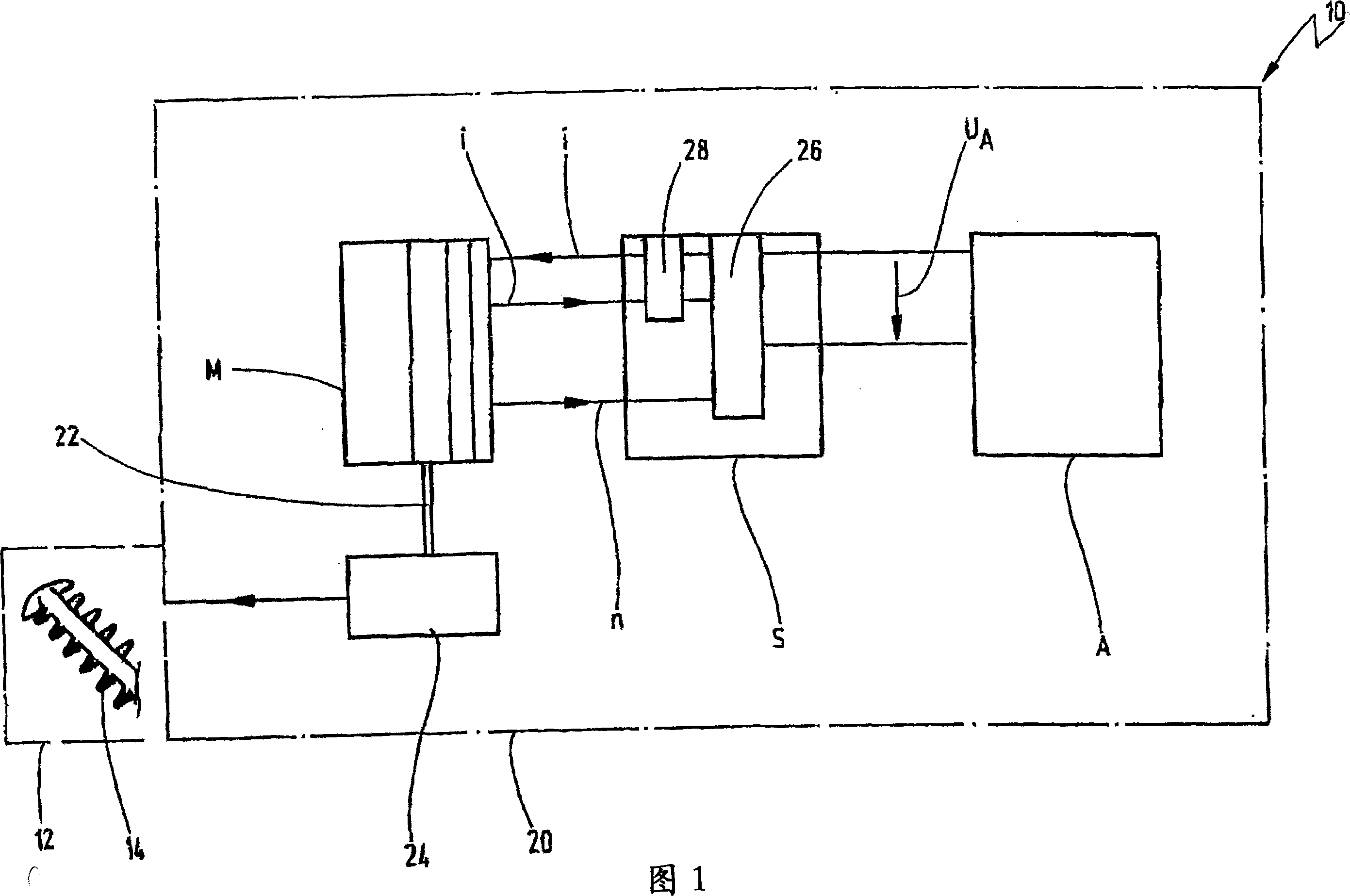
[0059] In FIG. 1 , a working machine for use in agriculture, forestry or horticulture is schematically indicated at 10 .

[0060] The working machine 10 has a tool 12 , which in the present case is schematically shown as a blade 14 of a pruning shear, and a drive device indicated generally at 20 .

[0061] As shown by blade 14, the working machine may be a pruning shear. Other examples of working machines 10 according to the present invention include mowers, lawn edge trimmers, chainsaws, roadheaders, blowers, vacuum shredders, power mowers, cutters, vacuums (wet or dry), sprayers and hair dryers, pressure washers, lawnmowers and more.

[0062] The working machine 10 is preferably in the form of a manual working machine that can be carried or manipulated by an operator. The working machine 10 is generally designed for professional use.

[0063] The drive device 20 has an electric motor M, a control device S and an electrical energy storage device A in the form of a recharge...


PUM


Abstract

The invention provides a driving device (20) of a manual working machine (10) applied in agriculture, forestry and horticulture, comprising an electric motor (M), an energy storage device (A) and a control device used in the electric motor (M), the energy storage device (A) supplies power to the electric motor, wherein the electric motor (M) comprises a special and linear characteristic curve (30) formed by current (i) consumed by the electric motor (M) and rotating speed (n) of output shaft (22) of the electric motor (M), the control device (S) comprises a current limiting device (26) for limiting current passing through the electric motor (M) under a maximal value, in order to prevent overload on the electric motor (M), wherein the control device (S) limits current consumption of the electric motor (M) in low rotating speed at a number far less than the characteristic curve value, the characteristic value can be used as function of rotating speed capable of being obtained via characteristic curve (30) of the electric motor (M) according to the rotating speed.

Description

technical field [0001] The invention relates to a drive device for a mobile, in particular manual or portable, agricultural, forestry and gardening machine, comprising an electric motor, an electrical energy storage device and a control device for the electric motor powered by the energy storage device, The current consumed by the motor and the rotational speed of the output shaft of the motor form a specific, in particular linear, characteristic curve of the motor, the control device having a current limiting device for limiting the current flowing through the motor to a maximum value, so that Protect the motor from overloading. [0002] The invention also relates to a corresponding method of controlling an electric motor, and also to a manual working machine for agriculture, forestry and horticulture comprising such a drive. Background technique [0003] In almost all fields of electrical engineering it is known to use current limiting devices to prevent overloading of cu...

Claims


Application Information

Patent Timeline
IPC IPC(8): H02P29/02A01G23/00
CPCH02P1/18H02P6/181H02H7/0858A01D75/182H02P29/028A01G3/053H02P6/06A01D69/02H02P29/032
Inventor H·罗斯坎普
Owner ANDREAS STIHL AG & CO KG
Why Eureka
Try Eureka