Filter device with a partition

A filter device and spacer technology, which is applied in the directions of dispersed particle filtration, separation method, charging system, etc., can solve problems such as engine combustion interference, and achieve the effect of low cost

Inactive Publication Date: 2008-09-03
CARL FREUDENBERG KG
View PDF0 Cites 6 Cited by
  • Summary
  • Abstract
  • Description
  • Claims
  • Application Information

AI Technical Summary

Problems solved by technology

Combustion in the engine is thereby significantly disturbed

Method used


Image

  • Filter device with a partition
  • Filter device with a partition
  • Filter device with a partition

Examples


Embodiment Construction

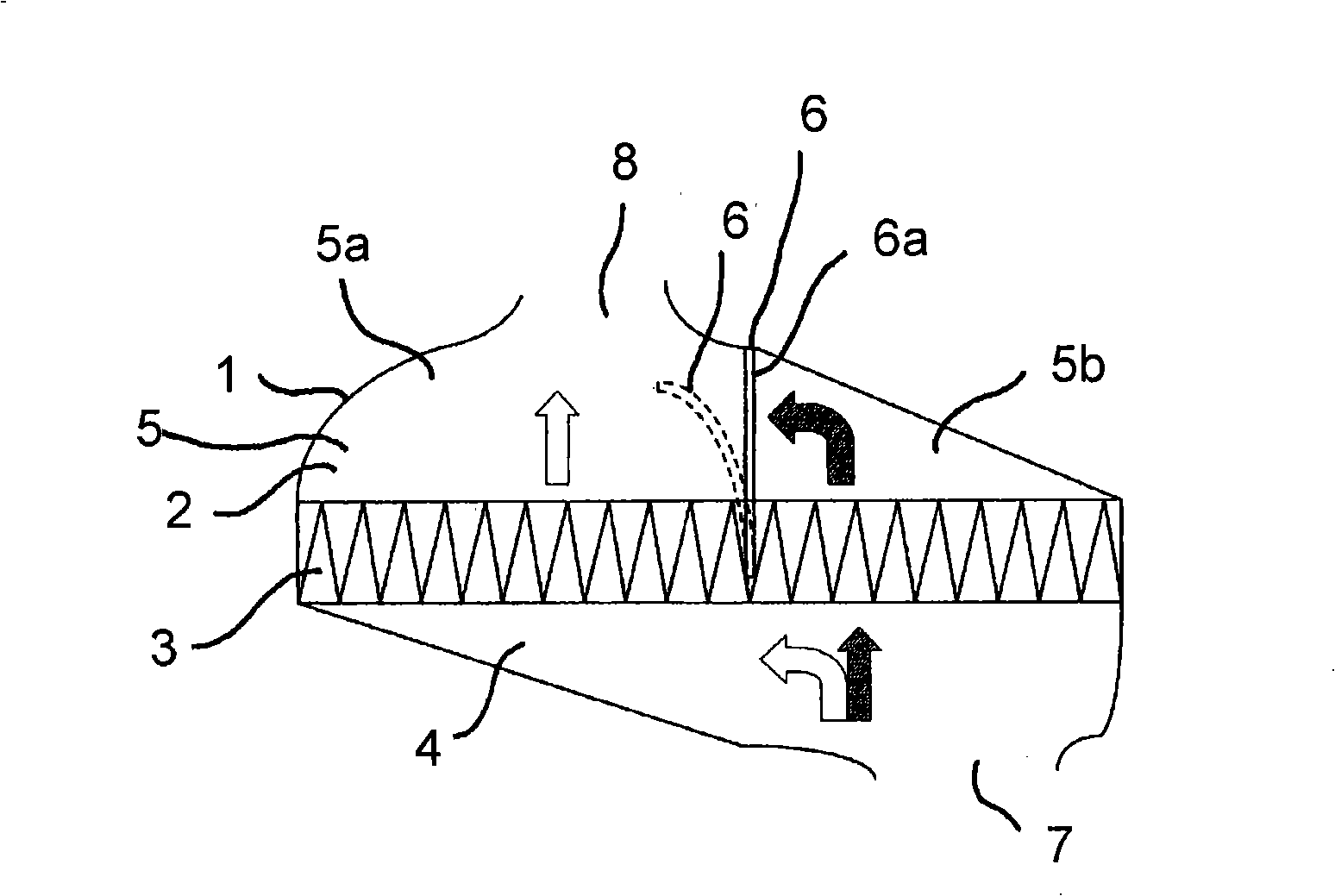
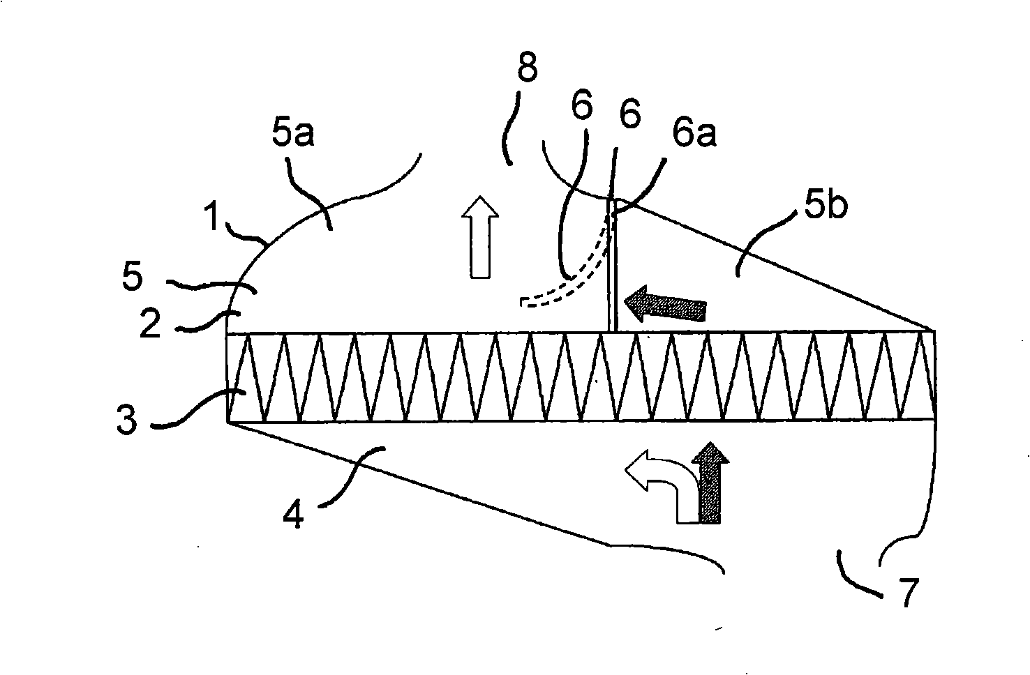
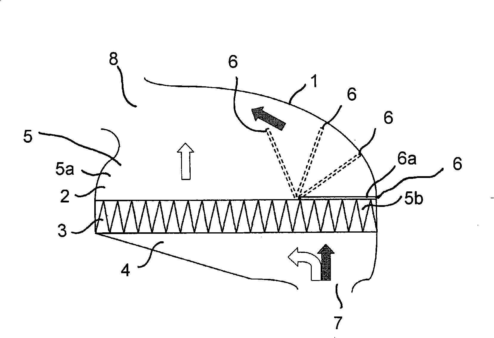
[0028] figure 1 A filter device for filtering a fluid medium, ie air for a car engine, is shown. The filter device comprises a housing 1 which accommodates a filter element 3 in a receiving chamber 2 . The filter element 3 divides the receiving chamber 2 into an inflow chamber 4 and an outflow chamber 5 . The receiving chamber 2 is divided in such a way that dirt particles separate the inflow chamber 4 from the outflow chamber 5 in a sealed manner. The filter element 3 can be glued or welded on the inner wall of the housing 1 . The outflow chamber 5 is divided by an at least partially movable partition 6 into a main chamber 5a and a secondary chamber 5b. When the partition 6 moves, the primary chamber 5a and the secondary chamber 5b are fluidly connected.

[0029] The spacer 6 has a working surface 6a on which the force generated by the pressure difference existing between the inflow chamber 4 and the outflow chamber 5 can act in such a way that the main chamber 5a and the...


PUM


Abstract

The invention relates to a filter device for filtering fluid media, comprising a housing (1) for accommodating a filter element (3) in an accommodation cavity (2), the filter element (3) divides the accommodation cavity (2) into an inflow cavity (4) and an outflow cavity (5) divided into a master cavity (5a) and a slavery cavity (5b) by a partition (6) at least partially movable, and the master cavity (5a) and the slavery cavity (5b) are flowably connected. The invention aims to provide a filter device capable of optimizing the air supply of an internal combustion engine after long running time at low cost, characterized in that the partition (6) has a working surface (6a), a force generated by a pressure difference between the inflow cavity (4) and the outflow cavity (5) can be applied to the working surface, such that the flowable connection between the master cavity (4) and the slavery cavity (5) can be formed directly by the force.

Description

technical field [0001] The invention relates to a filter device for filtering a fluid medium, comprising a housing which accommodates a filter element in a receiving chamber, wherein the filter element divides the receiving chamber into an inflow chamber and an outflow chamber. The outflow chamber is divided into a main chamber and a secondary chamber by an at least partially movable partition and the primary chamber and the secondary chamber are in flow communication. Background technique [0002] Filter devices for filtering fluid media are known from the prior art. These filter units are commonly used in automobiles, where the filter element is used to filter the intake air of the engine. The internal combustion engine then draws in the air filtered by the filter element through an outflow channel. Unfiltered air is delivered to the intake side of the filter element via an inflow channel. However, an asymmetrical flow regime results within the housing, depending on the...

Claims


Application Information

Patent Timeline
IPC IPC(8): B01D46/10B01D46/52B01D46/42F02M35/024
CPCB01D46/0087B01D46/521B01D46/58
Inventor U·施塔尔U·费尔伯
Owner CARL FREUDENBERG KG
Why Eureka
Try Eureka