
Multipurpose engine equipped with a canister

A technology of poison filter and engine, which is applied in the direction of machines/engines, engine components, combustion engines, etc., and can solve the problems of reduced adsorption efficiency and poor ventilation resistance

Active Publication Date: 2012-07-04
MITSUBISHI HEAVY IND MEIKI ENGINES CO LTD
View PDF1 Cites 0 Cited by
  • Summary
  • Abstract
  • Description
  • Claims
  • Application Information

AI Technical Summary

Problems solved by technology

However, halving the cross-section and doubling the channel length will reduce the adsorption efficiency
In addition, when the air is purged of adsorbed fuel, the ventilation resistance becomes significantly worse

Method used


Image

  • Multipurpose engine equipped with a canister
  • Multipurpose engine equipped with a canister
  • Multipurpose engine equipped with a canister

Examples


Embodiment Construction

[0025] Hereinafter, aspects of the present invention will be explained through embodiments based on the drawings. However, dimensions, materials, shapes, relative arrangements, etc. will be used for illustration only, and should not be construed as limiting the scope of the present invention unless any particular mention is made.

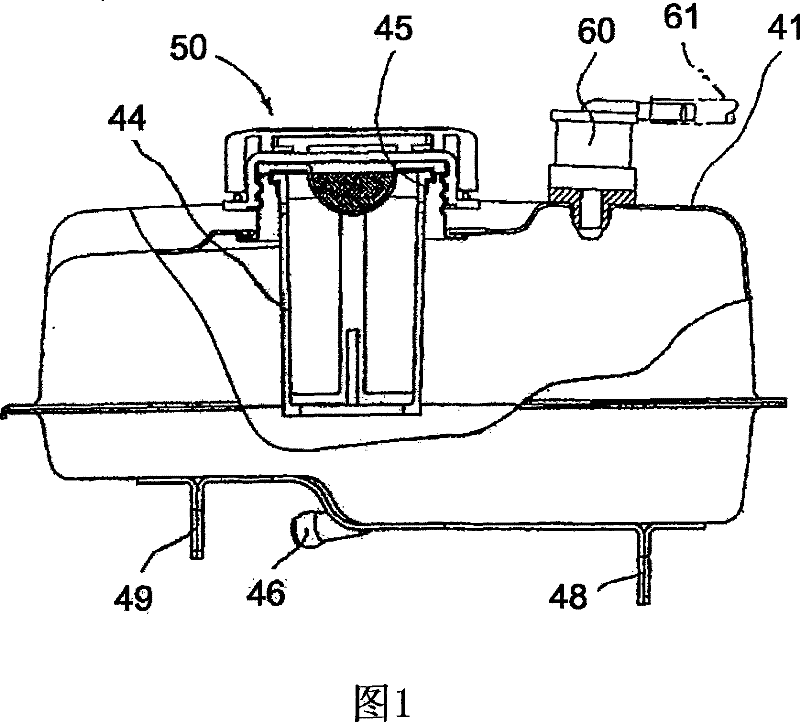
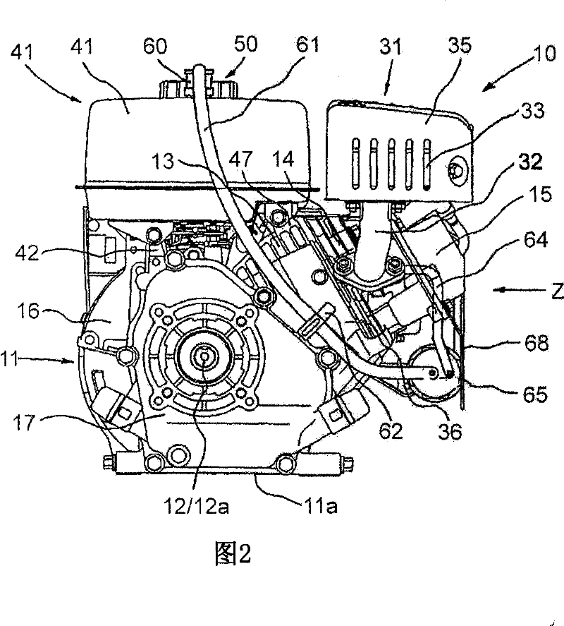
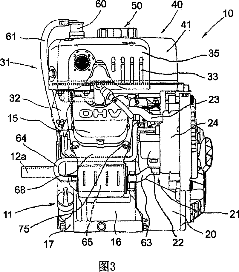
[0026] figure 1 is a partially cutaway side view of a fuel tank according to an embodiment of the present invention, with the tank cap and the vicinity of the fuel supply port shown in cross section. figure 2 is a front view of a multi-purpose engine capable of being compliant with transpiration gas regulations in accordance with the present invention. image 3 From figure 2 Side view of the engine seen in the direction of the Z arrow. Figure 4 is a cross-sectional view of the box cap assembly without the attachment cords to prevent it from falling out.

[0027] figure 2 and 3 The utility engine 10 in is, for example, an air-cooled single-...


PUM


Abstract

The present invention relates to a multipurpose engine including a canister that adsorbs evaporated fuel generated in a fuel tank as well as desorbs a desorbs the fuel so that the fuel can be led to an air suction system of the engine. A multipurpose engine, comprising: a charge line leading an evaporated fuel generated in a fuel tank to a canister whereby the evaporated fuel is adsorbed; and a purge duct line that leads the evaporated fuel desorbed in the canister to an air suction system of the engine; wherein, the fuel tank is structurally sealed, has no vent to the atmosphere, is provide with a fuel supply opening compatible with a cap assembly of a sealed structure and is provided with a rollover valve on a surface of the fuel tank; wherein, the fuel supply opening and the cap assembly form no vent except when the engine is refueled; and further wherein, the charge line leading the evaporated fuel is gas-tightly connected to a discharge port of the rollover valve.

Description

technical field [0001] The present invention relates to a multipurpose engine equipped with a canister which adsorbs fuel vapor evaporated in a fuel tank, wherein the fuel vapor desorbed from the canister is introduced into an air intake system of the engine. Background technique [0002] For a multipurpose engine that is in a stopped state or in operation, Patent Document 1 (JP: P2005-163690A) or 2 (JP: P2005-163688A) discloses a method of preventing fuel vapor leakage around the engine. [0003] In other words, Patent Document 1 discloses a method of preventing fuel vapor generated in a fuel tank from leaking to the outside through the steps of: providing a filter that absorbs evaporated fuel generated in the fuel tank using a detachable tank cap; provide a charging line connecting the inside of the fuel tank and the filter; make the connected tank cap form a part of the charging line; and make the charging line pass inside the tank, and Patent Document 2 discloses a metho...

Claims


Application Information

Patent Timeline
Patent Type & Authority Patents(China)
IPC IPC(8): F02M25/08F02M37/00
CPCB60K2015/03105Y02T10/126B60K15/0406F02M25/089F02M33/08F02M37/20B60K15/03504B60K2015/03236B60K2015/03557B60K2015/0451B60K15/03519
Inventor 伊藤千哉也牧和宏
Owner MITSUBISHI HEAVY IND MEIKI ENGINES CO LTD
Learn More