Cab for construction machine

a construction machine and cab technology, applied in the direction of doors, roofs, tractors, etc., can solve the problems of high manufacturing cost, complex structure, and difficulty in mounting the rectangular parallelepiped cab of necessary size within the rotation radius of the turntable, and achieve the effect of low cost, easy construction, and simple structur

Inactive Publication Date: 2007-07-24
KOMATSU LTD
View PDF23 Cites 53 Cited by
  • Summary
  • Abstract
  • Description
  • Claims
  • Application Information

AI Technical Summary

Benefits of technology

[0015]The present invention has been made in light of the foregoing problems. It is an object of the invention to provide a construction machine's cab that can be manufactured at low cost and can easily secure rollover protection strength.

Problems solved by technology

In the above-described structure, however, in a case where the hydraulic shovel or truck crane is small-sized, there is the problem that it is difficult to mount a rectangular parallelepiped cab of necessary size within the radius of rotation of the turntable.
(1) The cab 73 has the four pillars at the four corners (i.e., front, rear, left, and right corners) and has one pillar at the bulging portion of the outer side surface portion 80 (only outer pillars 81, 82, and 83 are shown). Therefore, there are many pillars. The structure is complex. Consequently, the manufacturing cost is high.
(2) In spite of having the five pillars, only one intermediate pillar 81 is present in the center of the cab 73. Where the cab 73 of this structure is so constructed that when the hydraulic shovel 70 rolls over, the cab is strong enough to withstand the crush and secure a required space inside (hereinafter referred to as the rollover protection strength) it is necessary to reinforce all of the pillars at the four corners of the cab 73 and beams connecting top portions of the pillars (only outer beam 87 is shown). Hence, the manufacturing cost of the cab is quite high.
(3) Another conceivable method to give the cab a structure having rollover protection strength comprises mounting a separate gate-shaped rollover guard across the cab. In this case, however, the cost of the rollover guard is produced. In addition, there arises the problem that the rollover guard protrudes outside the radius of rotation of the turntable 72. That is, it is required that the cab and rollover guard be contained within the radius of rotation of the turntable.

Method used


Image

  • Cab for construction machine
  • Cab for construction machine
  • Cab for construction machine

Examples


Embodiment Construction

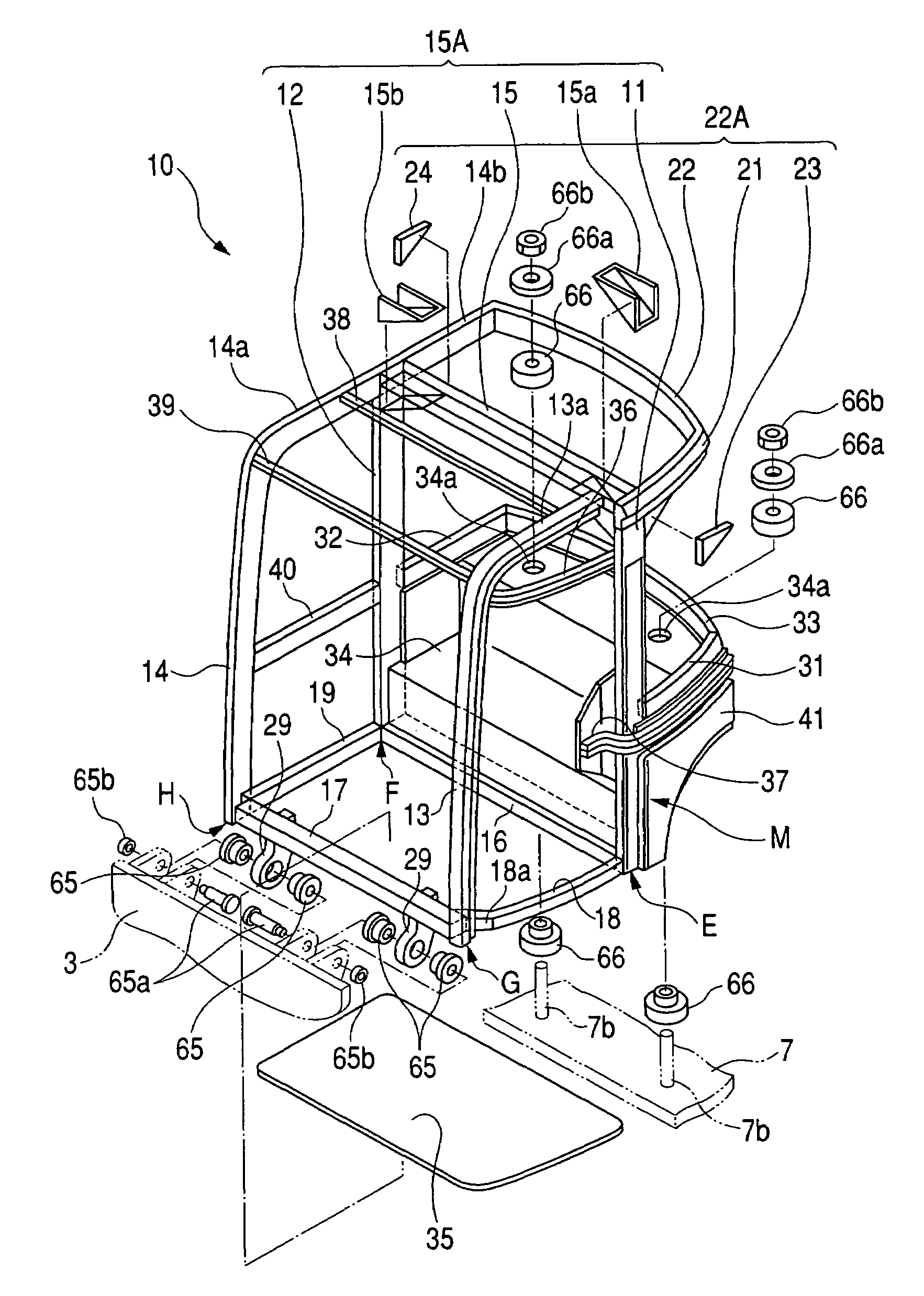
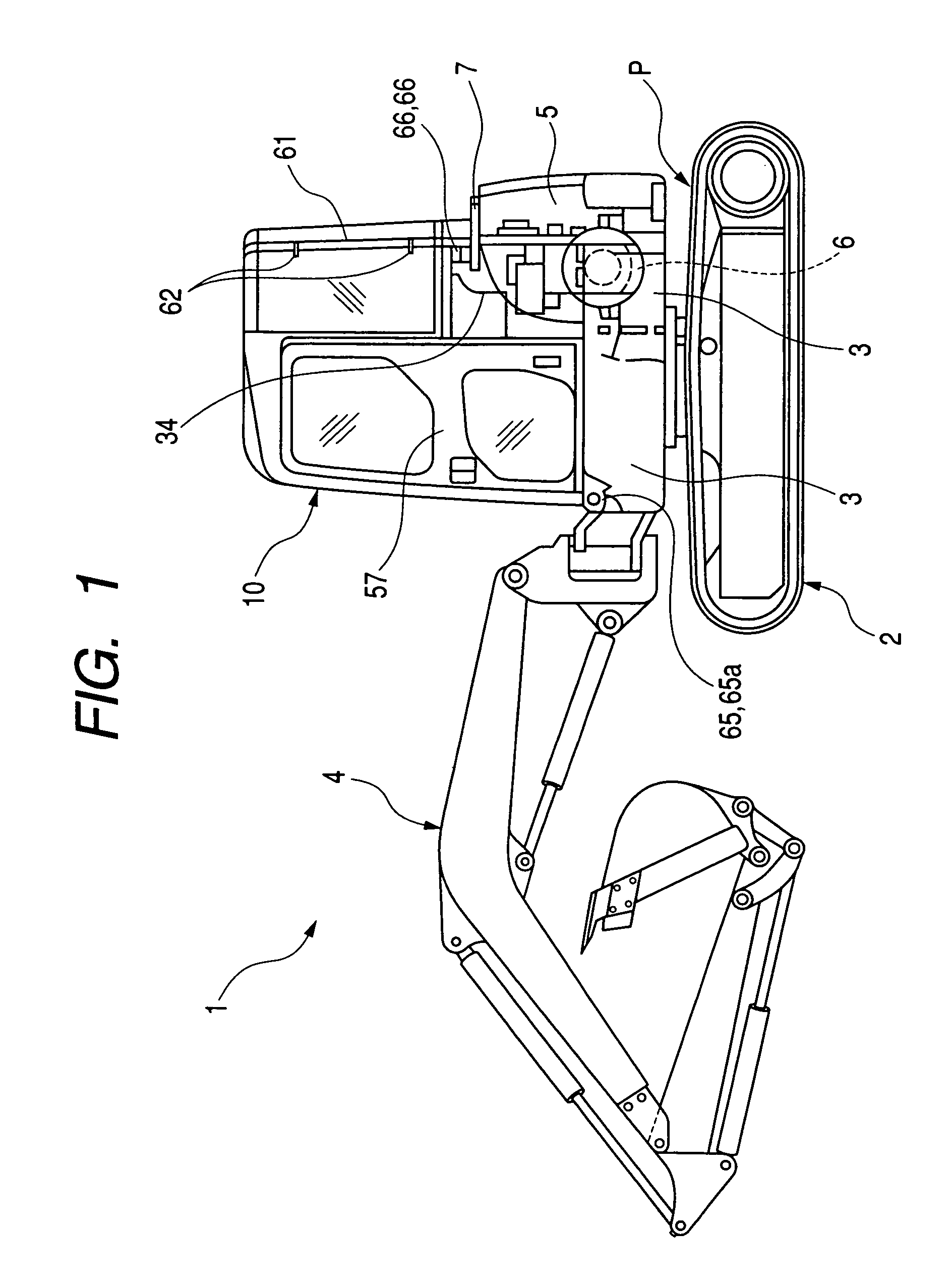
[0039]Embodiments of construction machine cabs according to the present invention are hereinafter described in detail with reference to the drawings by taking a hydraulic shovel as an example.

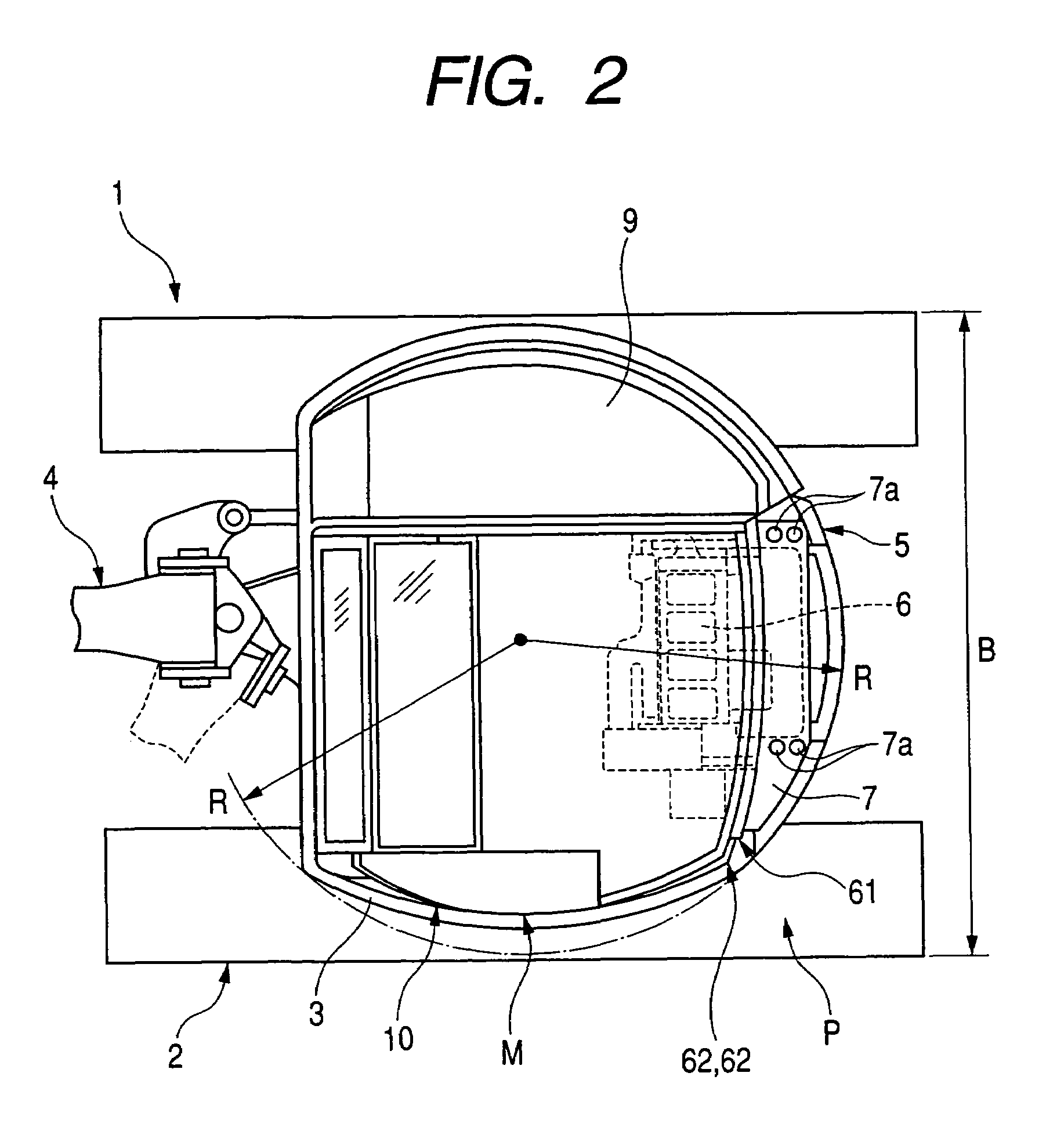
[0040]Turning first to FIGS. 1 and 2, a hydraulic shovel 1 has a traveling gear 2 and a turntable 3 rotatably mounted on the top surface of the locomotive body 2. A working machine 4 is mounted to the front portion of the turntable 3. A counter weight 5 is disposed at the rear end of the rear portion of the turntable 3. An engine 6 is disposed adjacent to the front of the counterweight 5. A cab 10 is placed on the left front portion of the turntable 3 so that the operator can get an unobstructed view of the front-end portion of the working machine 4. A machine compartment 9 accommodating a fuel tank, an oil tank for operations, control valves, and so on (not shown) is disposed adjacent to the right side of the cab 10.

[0041]Furthermore, in order to secure necessary volume of the cab 10, the rear...


PUM


Abstract

A cab capable of easily securing rollover protection strength at low manufacturing cost is offered. Four pillars are mounted in the front and rear, and left and right of the cab. Two of them are mounted respectively in a first position at the outer side portion where it bulges outward and in a second position on the inner side portion and opposite the first position in the left-and-right direction. At least one of the pillars is formed with a pipe. A U-shaped frame is firmly mounted between the upper ends of the left and right rear pillars among the four pillars, and directed rearward to form a U-shaped rear roof frame.

Description

BACKGROUND OF THE INVENTION[0001]1. Field of the Invention[0002]The present invention relates to a cab for a construction machine.[0003]2. Description of the Related Art[0004]Small-sized hydraulic shovels conventionally frequently used in civil engineering works, or truck cranes often used for assembling steel structures of small buildings in urban areas, must be operated in narrow places. Therefore, a turntable is mounted at the upper portion of the traveling gear. A working machine such as a shovel machine or crane machine is disposed on the turntable. An operator's cab (hereinafter simply referred to as the cab) is disposed at a position offset left or right from the working machine. The operator can get an unobstructed view of the front-end portion of the working machine. Furthermore, the cab is so designed not to protrude outside the radius of rotation of the outer fringes of the turntable. In this way, considerations are given not to interfere with surrounding structures and s...

Claims


Application Information

Patent Timeline
Patent Type & Authority Patents(United States)
IPC IPC(8): B60R21/13B62D33/06B60J5/00B60J5/06B62D25/08E02F9/16
CPCE02F9/163
Inventor SHIOJI, HIROYUKINAMURA, AKIHIDEITOH, TATSUSHI
Owner KOMATSU LTD
Why Eureka
Try Eureka