
Vehicle stability control system with tire monitoring

a technology of vehicle stability control and monitoring system, which is applied in the direction of underwater vessels, registering/indicating the working of vehicles, and non-deflectable wheel steering, etc., can solve the problems of occupants outboard, limited ability of conventional stability control systems to mitigate, and less effective, so as to achieve the effect of mitigating a vehicle rollover even

Inactive Publication Date: 2010-08-17
FORD GLOBAL TECH LLC
View PDF18 Cites 53 Cited by
  • Summary
  • Abstract
  • Description
  • Claims
  • Application Information

AI Technical Summary

Benefits of technology

The present invention provides a control system for a vehicle that includes a tire sensor and a vehicle dynamics sensor. The system analyzes data from the tire sensor and the vehicle dynamics sensor to determine the status of the tires and the stability of the vehicle. The system can adjust stability control functions accordingly to improve system response and effectiveness. The control system can also allow for quicker or earlier and softer stability control interventions at low tire pressure or slip levels. The technical effects of the invention include improved stability control and reduced brake pressure application.

Problems solved by technology

However, tripped rollover events, such as hitting a curb while sliding laterally, generate significant lateral forces which can move an occupant outboard, often before the vehicle has experienced enough roll angle to be detected by the roll and yaw sensors.
Thus, conventional stability control systems are limited in their ability to mitigate and prevent tripped rollover events.
When tire pressure is low, however, such RSC system interventions can be less effective and even lead to tire-debeading.
Debeading of a tire can result in rim or wheel contact with a road surface and resultant vehicle instability.

Method used


Image

  • Vehicle stability control system with tire monitoring
  • Vehicle stability control system with tire monitoring
  • Vehicle stability control system with tire monitoring

Examples


Embodiment Construction

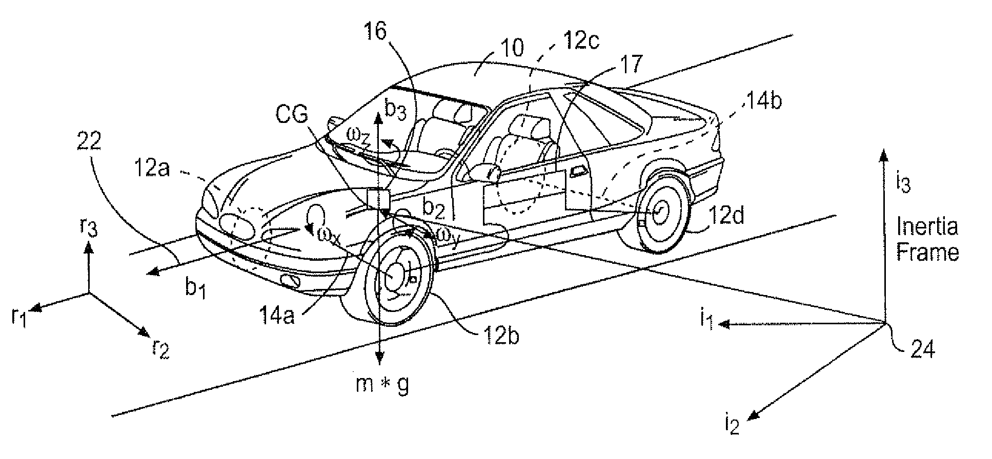
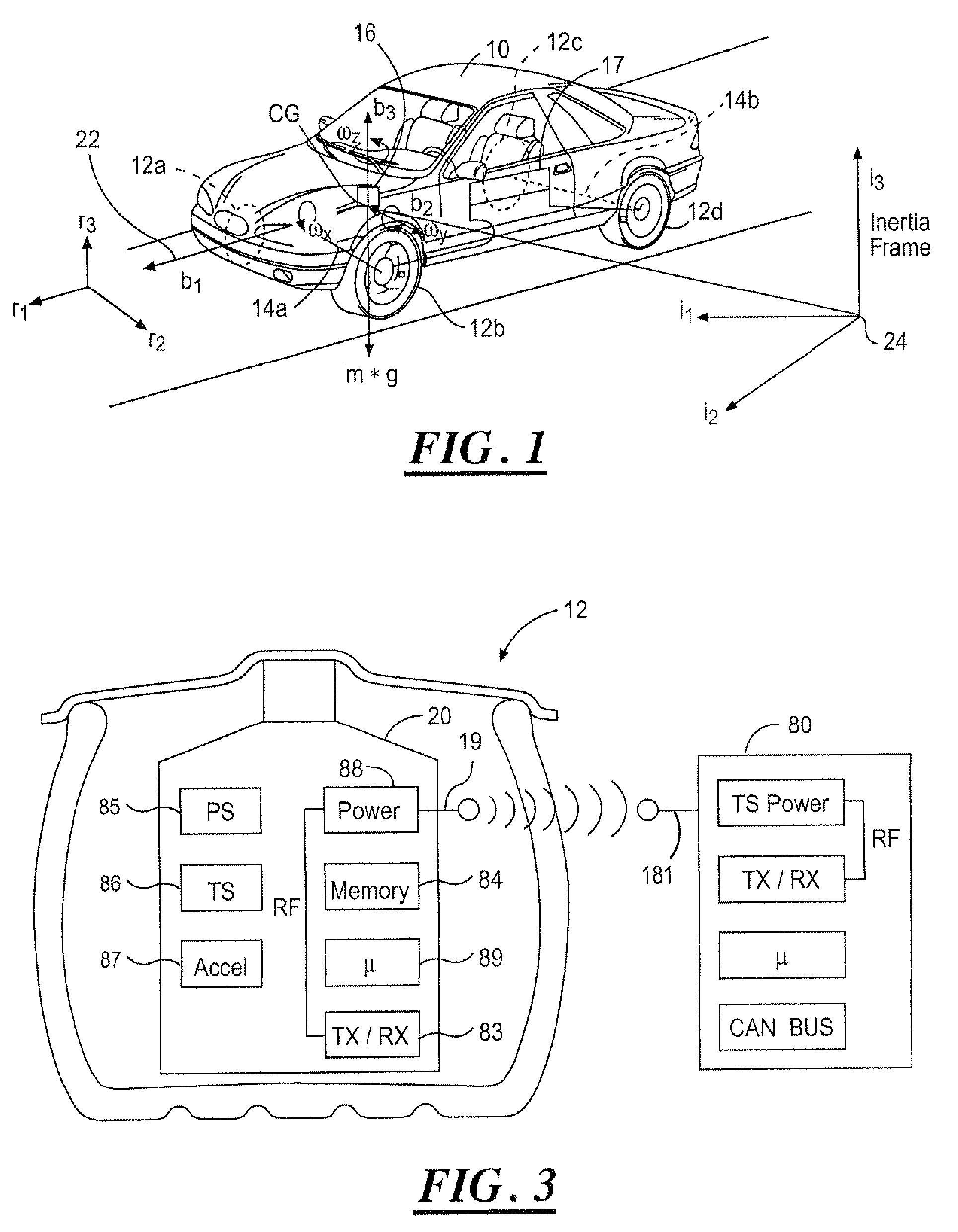
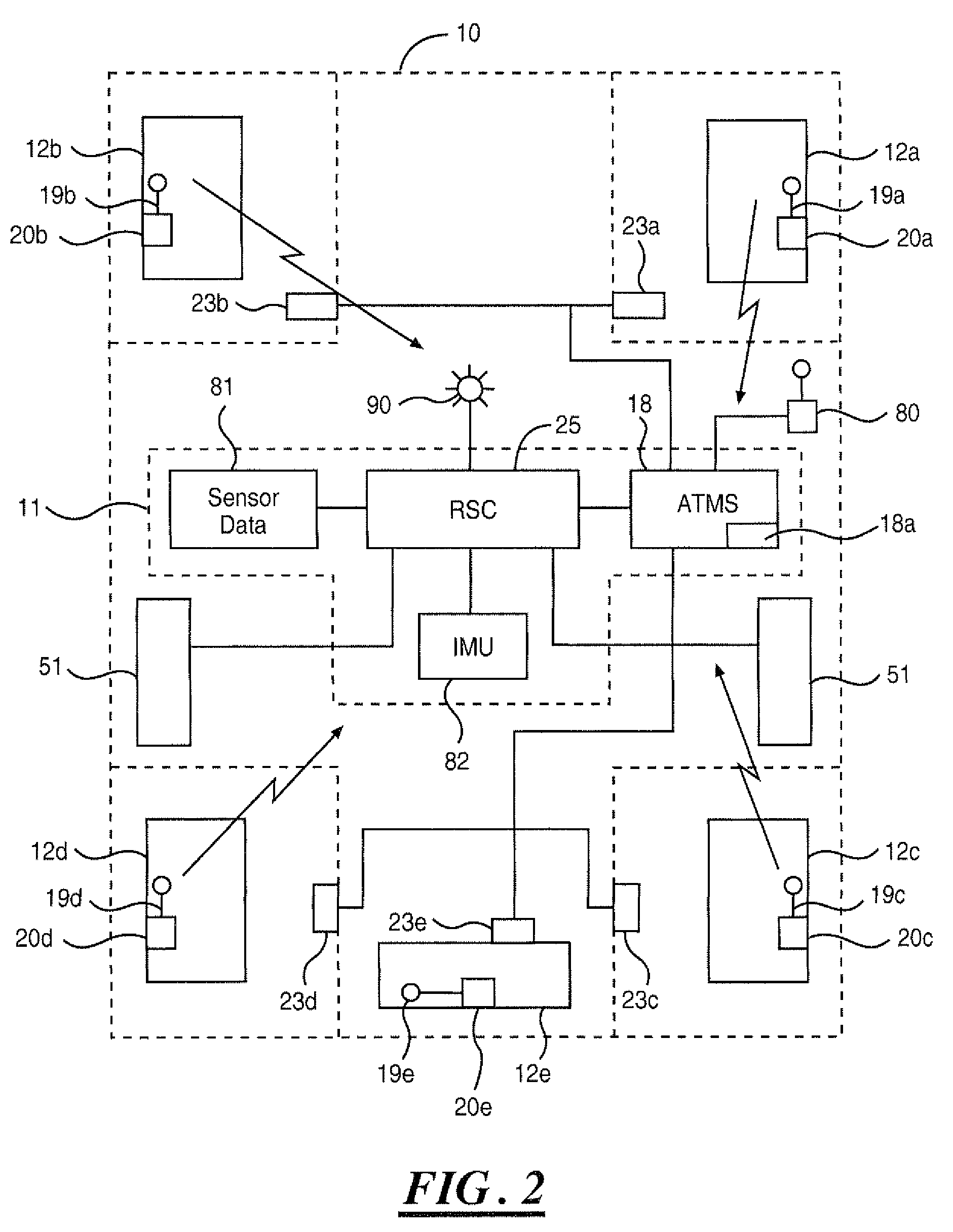
[0026]In the following figures, the same reference numerals will be used to identify the same components. The present invention may be used in conjunction with vehicle control systems including a yaw stability control (YSC) system, roll stability control (RSC) system, lateral stability control (LSC) system, integrated stability control (ISC) system, or a total vehicle control system for achieving desired vehicle performance. The present invention is also described with respect to an integrated sensing system (ISS), which uses a centralized motion sensor cluster such as an inertial measurement unit (IMU) and other available, but decentralized, sensors. Although a centralized motion sensor, such as an IMU, is primarily described, the techniques described herein are easily transferable to using the other discrete sensors.

[0027]In the following description, various operating parameters and components are described for several constructed embodiments. These specific parameters and compon...


PUM


Abstract

A control system (10) for a vehicle (16) includes a sensor (35-47) that generates a sensor signal and a stability control system (26). Tire monitoring sensors (20) in each wheel generate tire signals including temperature, pressure and acceleration. The controller (26) is coupled to the sensors (20, 25-47), and generates a first roll condition signal as a function of the sensor signal, and generates a second roll condition signal as a function of the tire signals. The first or second roll condition signals control the rollover control system to mitigate a vehicle rollover event.

Description

TECHNICAL FIELD[0001]The present invention relates generally to vehicle stability control systems and tire monitoring systems. More particularly, the present invention is related to improving rollover detection by signal analysis of tire pressure, temperature and acceleration data.BACKGROUND[0002]Stability control systems currently exist in various forms such as electronic stability control systems (ESC), yaw stability control systems (YSC), and roll stability control systems (RSC). Such systems are used to maintain controlled and stable vehicle operations for improved vehicle and occupant safety. Stability control systems are often used to maintain vehicle traction and to prevent or mitigate a rollover event.[0003]Current stability control systems are well adapted for ride comfort and road handling. The sensing systems for detecting rollover events rely on yaw and roll rate sensors and accelerometers to determine if the vehicle has exceeded the limits of lateral stability. These sy...

Claims


Application Information

Patent Timeline
Patent Type & Authority Patents(United States)
IPC IPC(8): G05D1/00
CPCB60C23/0408B60T7/22B60T8/1725B60T8/17554B60T2230/03B60T2240/06B60W30/04B60W2420/52B60W2420/408
Inventor RAO, MANOHARPRASAD K.CUDDIHY, MARK A.BUJAK, CHRISTOPHER R.
Owner FORD GLOBAL TECH LLC
Learn More