
A Composite Accelerometer Based on Capacitance Effect and Tunnel Effect

An accelerometer and tunnel effect technology, applied in the field of micro-inertial navigation, can solve the problems of limited range, easily damaged tunnel tip, poor anti-overload ability, etc., achieve wide detection range, easy to use, and avoid damage to devices

Active Publication Date: 2016-06-08
ZHONGBEI UNIV
View PDF4 Cites 0 Cited by
  • Summary
  • Abstract
  • Description
  • Claims
  • Application Information

AI Technical Summary

Problems solved by technology

However, since the distance between the tunnel tip and the electrode plate must be at the nanometer level during operation, the measuring range is limited, the overload resistance is poor, and the tunnel tip is easily damaged when the overload is high.

Method used


Image

  • A Composite Accelerometer Based on Capacitance Effect and Tunnel Effect
  • A Composite Accelerometer Based on Capacitance Effect and Tunnel Effect
  • A Composite Accelerometer Based on Capacitance Effect and Tunnel Effect

Examples


Embodiment Construction

[0027] Embodiments of the present invention are described in detail below, examples of which are shown in the drawings, wherein the same or similar reference numerals designate the same or similar elements or elements having the same or similar functions throughout. The embodiments described below by referring to the figures are exemplary only for explaining the present invention and should not be construed as limiting the present invention.

[0028] In the description of the present invention, it should be understood that the orientations or positional relationships indicated by the terms "center", "upper", "lower", "front", "rear", "left", "right" etc. are based on the attached The orientation or positional relationship shown in the figure is only for the convenience of describing the present invention and simplifying the description, and does not indicate or imply that the referred device or element must have a specific orientation, be constructed and operated in a specific ...


PUM


Abstract

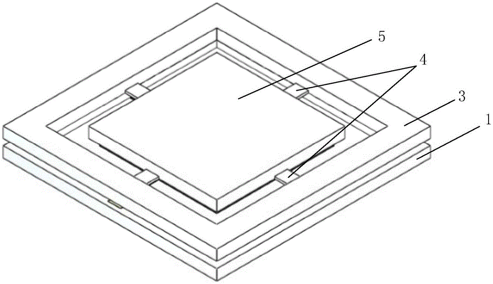
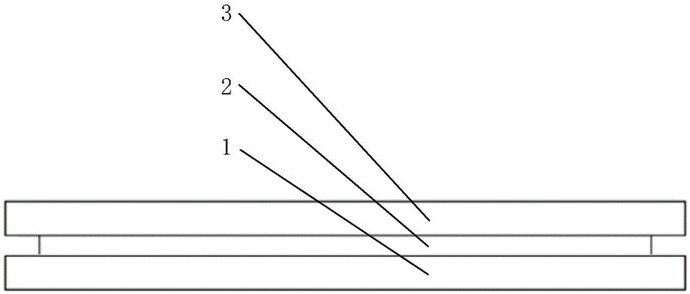
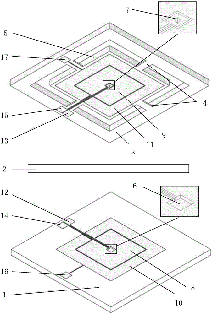
The invention discloses a composite accelerometer based on capacitance effect and tunnel effect, comprising: a bonded substrate, a pad frame, a support frame, a cantilever beam, a quality block, and a tunnel tip arranged at the center of the lower surface of the mass block. The beneficial effect of the present invention is that the integration of capacitance detection and tunnel effect detection is adopted, which has the advantages of both capacitance detection and tunnel detection, and can realize low detection threshold, wide range and high sensitivity detection of acceleration; at the same time, it can be used in environments with known acceleration values Accurate measurement of the acceleration, using integrated design, reasonable structure, high sensitivity, simple detection circuit, easy to use, good reliability, suitable for miniaturization.

Description

technical field [0001] The invention relates to the related field of micro-inertial navigation technology, in particular to a composite micro-mechanical accelerometer based on capacitance effect and tunnel effect. Background technique [0002] With the development of micromechanical system (MEMS) technology, it has the characteristics of low cost, small size, easy mass production and good integration, and has attracted more and more attention from people, and has been widely used in civilian and military fields. . However, due to the limitation of key performance indicators, micromechanical sensors have not been fully applied in military, aerospace, aviation and other cutting-edge fields. Among them, sensitivity and measuring range are key indicators for micromechanical sensors to be improved. For sensors manufactured using mainstream principles, high sensitivity is usually accompanied by small measuring range and low overload. [0003] With the development of science and ...

Claims


Application Information

Patent Timeline
Patent Type & Authority Patents(China)
IPC IPC(8): G01P15/125B81B7/02
Inventor 李孟委王莉褚伟航蒋孝勇程壑刘俊李博黄用
Owner ZHONGBEI UNIV
Learn More