Back ring type coupled aerial

A technology for coupling antennas and coupling parts, applied in the direction of antenna grounding switch structure connection, radiation element structure, etc., can solve problems such as narrow capacitive coupling area, shorten antenna configuration length, and inability to truly apply electronic products, etc., to achieve increased operating bandwidth , Shorten the configuration length and increase the convenience of configuration

Inactive Publication Date: 2008-09-03
连展科技电子(昆山)有限公司
View PDF1 Cites 10 Cited by
  • Summary
  • Abstract
  • Description
  • Claims
  • Application Information

AI Technical Summary

Problems solved by technology

The above design uses meandering inductance to increase the electrical coupling efficiency and shorten the length of the antenna configuration. Although it can achieve the purpose of multi-frequency operation and size reduction, due to the narrow capacitive coupling area and the upper limit of the antenna operating bandwidth, Cannot be used in various electronic products

Method used


Image

  • Back ring type coupled aerial
  • Back ring type coupled aerial
  • Back ring type coupled aerial

Examples


Embodiment Construction

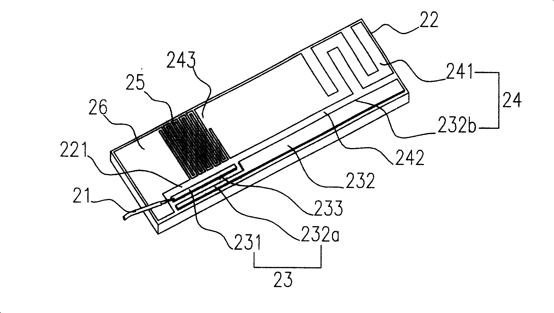
[0017] see figure 2 , is a three-dimensional schematic diagram of the first embodiment of the present invention, including: a feed-in line 21, a substrate 22, a coupling conductor 232, a first coupling portion 23, a second coupling portion 24, a second conductor 25 and a ground plane 26 . The substrate 22 has a surface 221; the coupling conductor 232 is divided into a first coupling region 232a and a second coupling region 232b; the first coupling portion 23 includes: a feeding conductor 231 and the first coupling region 232a, and the first coupling A gap is formed between the region 232a and the feeding conductor 231; the second coupling portion 24 is composed of the second coupling region 232b and a first conductor 241, and there is a distance between the first conductor 241 and the second coupling region 232b.

[0018] Wherein the first coupling part 23 and the second coupling part 24 are located on the surface 221 of the substrate 22, the length of the substrate 22 is ab...


PUM


Abstract

The invention provides a loop type coupling antenna, which includes: a feed-in wire, a coupling conductor, a first coupling part, a second coupling part, a second conductor and a ground surface, one end of the coupling conductor belongs to the first coupling part, another end belongs to the second coupling part; the feed-in wire connects with the first coupling part for providing a feed-in signal to the first coupling part; the feed-in signal couples to the second coupling part through the coupling conductor; one end of the second conductor connects with the second coupling part, another end connects with the ground surface that conduct signal of the second coupling part to the ground surface by using the second conductor. Impedance match can be adjusted efficiently by using the first coupling part, and antenna operation frequency width can be increased. The second coupling part and the second conductor reduce resonant frequency, and shorten wavelength of resonant path center frequency.

Description

technical field [0001] The invention relates to a loop coupling antenna, in particular to an antenna with dual coupling induction units. Background technique [0002] The progress of wireless communication transmission technology has made the functions of various related auxiliary products more and more advanced, especially the transmission efficiency and size requirements of antennas, which often affect the sales volume of manufacturers' products in the market. How to effectively integrate multi-band transmission performance of antennas, Simultaneously, reducing the configuration space of the antenna inside the electronic device has become an important subject for various related businesses to actively seek breakthroughs. [0003] To effectively reduce the size of antenna configurations while improving signal conduction efficiency, refer to figure 1 , is a three-dimensional schematic diagram of the United States patent announcement case number US6081242 "antenna matching c...

Claims


Application Information

Patent Timeline
Patent Type & Authority Applications(China)
IPC IPC(8): H01Q1/50H01Q1/38
Inventor 萧智仁廖柏渊邱宗文萧富仁
Owner 连展科技电子(昆山)有限公司
Why Eureka
Try Eureka