Esd type connector

An electrostatic discharge and connector technology, applied in the field of electrostatic discharge connectors, to avoid adverse effects and improve reliability

Inactive Publication Date: 2008-09-03
TYCO ELECTRONICS JAPAN GK
View PDF1 Cites 0 Cited by
  • Summary
  • Abstract
  • Description
  • Claims
  • Application Information

AI Technical Summary

Problems solved by technology

Therefore, the situation that static electricity cannot be ideally placed in the shielding path cannot be solved

Method used


Image

  • Esd type connector
  • Esd type connector
  • Esd type connector

Examples


Embodiment Construction

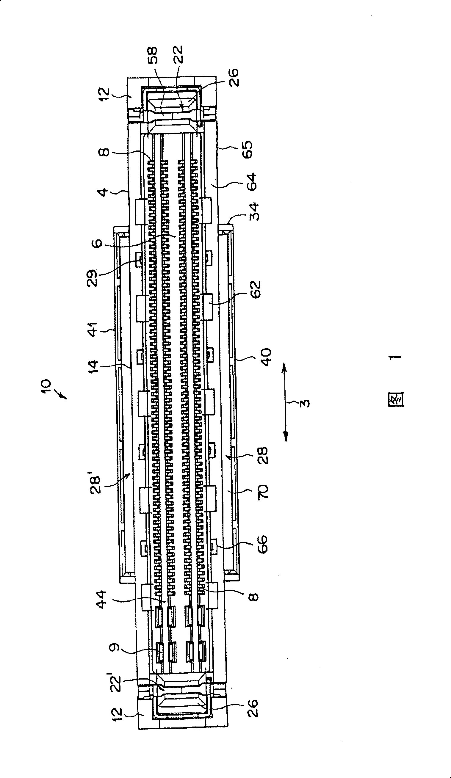
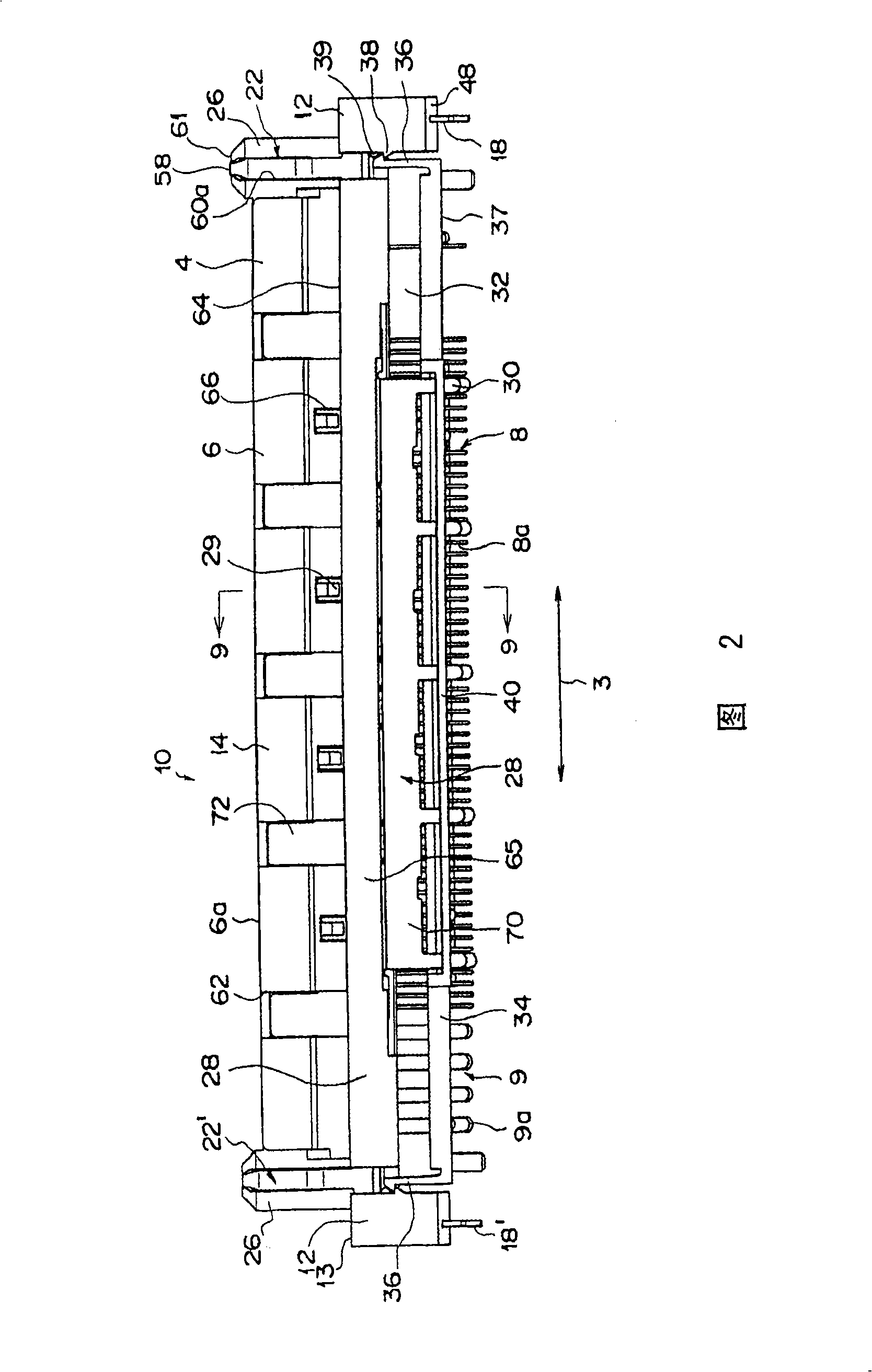
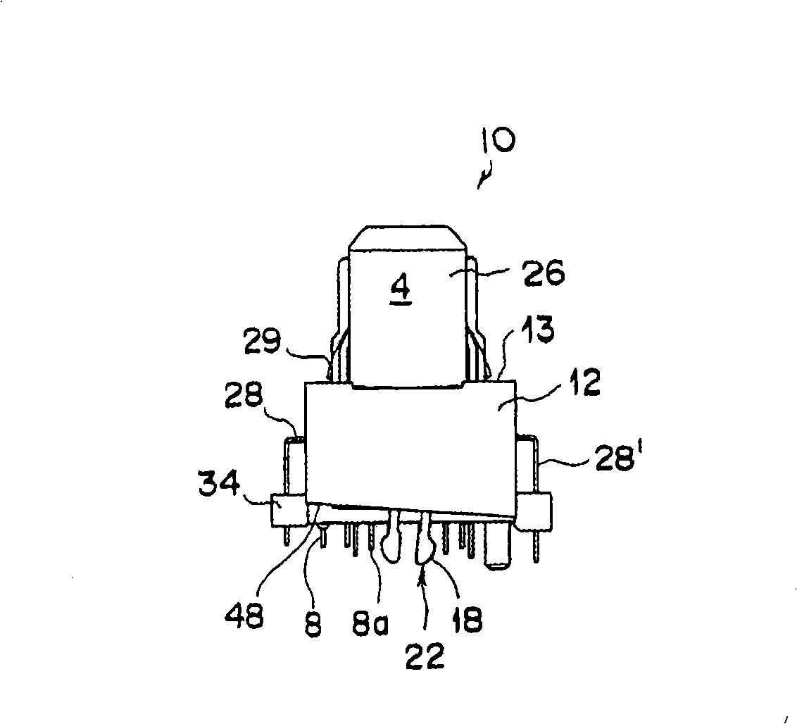
[0057] A preferred embodiment of the electrical connector of the present invention, that is, a plug connector (electrostatic discharge connector with guide bar), will be described in detail below with reference to the accompanying drawings. 1 to 4 show a plug connector 10 . Accompanying drawings 1, 2, 3 and 4 are plan view, front view, right side view and bottom view of the plug connector 10 respectively.

[0058] Description will be given below with reference to FIGS. 1 to 4 . The plug connector 10 comprises an elongated insulating housing 4 ; on a junction 6 of the housing 4 , contacts 8 and 9 arranged in four rows along the longitudinal direction 3 of the housing 4 . The contacts 8 are narrow contacts for signal transmission. The contacts 9 are wide contacts for the power supply. The housing 4 comprises a parallelepiped main body 14 extending in the longitudinal direction 3 and parallelepiped mounting portions 12 and 12 at both ends thereof. The main body 14 and the mou...


PUM


Abstract

When discharging in a static discharge connector having a guide rod and the static discharge connector having a guide hole, the discharge reliability is increased and the adverse effect of the contact to the shield member is avoided. The connector has an insulative housing having a contact; a condition member arranged on the joint surface of the insulative housing, wherein the insulative housing further includes a pair of guide holes and a shield member arranged on the outside of the insulative housing and connected with the circuit board; and a condition member through the pressing and bending a metal plate, wherein the condition member having a mounting part to connected with the circuit plate in the way independent of the shield member is arranged to make the pressing surface exposed on the inner wall of the guide hole; other condition materials are arranged in the groove formed on the top of the joint rib along the vertical direction. The groove is formed on the top of the joint rib along the vertical direction. The joint rib is integrally formed with the insulative housing in the joint notch of the insulative housing. The condition materials have a connecting part, wherein the connecting part is near one of the guide hole and contacted with the condition member.

Description

[0001] This application is a divisional case of an application with the same title filed on July 31, 2003 and with application number 03158027.0. technical field [0002] The invention relates to an electrostatic discharge connector, in particular to an electrostatic discharge connector with a guide rod, and an electrostatic discharge connector with a guide hole combined therewith. Background technique [0003] Generally, an electrical connector mounted on a printed circuit board (hereinafter referred to as "circuit board") is generally a device used to electrically connect circuit boards in a personal computer or similar equipment to each other, and the circuit board is equipped with electronic components . And for a laptop personal computer, the connection portion at the rear of the electrical connector is connected to each accessory. It is well known to provide guides for the connectors of electrical and electronic equipment to enable these connectors to engage each oth...

Claims


Application Information

Patent Timeline
Patent Type & Authority Applications(China)
IPC IPC(8): H01R13/652H01R13/648H01R12/24
CPCH01R13/6485H01R23/6873H01R12/716
Inventor 笹目直孝桥本信一
Owner TYCO ELECTRONICS JAPAN GK
Why Eureka
Try Eureka