Dust removing device for vacuum cleaner

A technology of dust removal device and vacuum cleaner, which is applied in the direction of suction filter, etc., which can solve the problems that the dust removal efficiency of the first-level dust collector cannot be improved, increase the number of times users clean the dust cup, and affect the dust removal efficiency of the vacuum cleaner, so as to improve the dust removal efficiency and reduce cleaning The number of dust cups and the effect of avoiding mutual influence

Active Publication Date: 2008-09-10
KINGCLEAN ELECTRIC GREEN TECH SUZHOU
View PDF0 Cites 13 Cited by
  • Summary
  • Abstract
  • Description
  • Claims
  • Application Information

AI Technical Summary

Problems solved by technology

[0004] With the strengthening of consumers' awareness of environmental protection and protection, the air discharged by the vacuum cleaner is required to be cleaner to avoid secondary pollution. Therefore, the vacuum cleaners currently on the market use two-stage dust removal, and the first-stage dust collector can be a filter cartridge or a cyclone. The second-stage dust collector is a cyclone cylinder. Although the shapes of the two-stage dust collectors are different, and the two-stage dust collectors can share or have dust collection chambers respectively, their layout adopts

Method used


Image

  • Dust removing device for vacuum cleaner
  • Dust removing device for vacuum cleaner
  • Dust removing device for vacuum cleaner

Examples


Example Embodiment

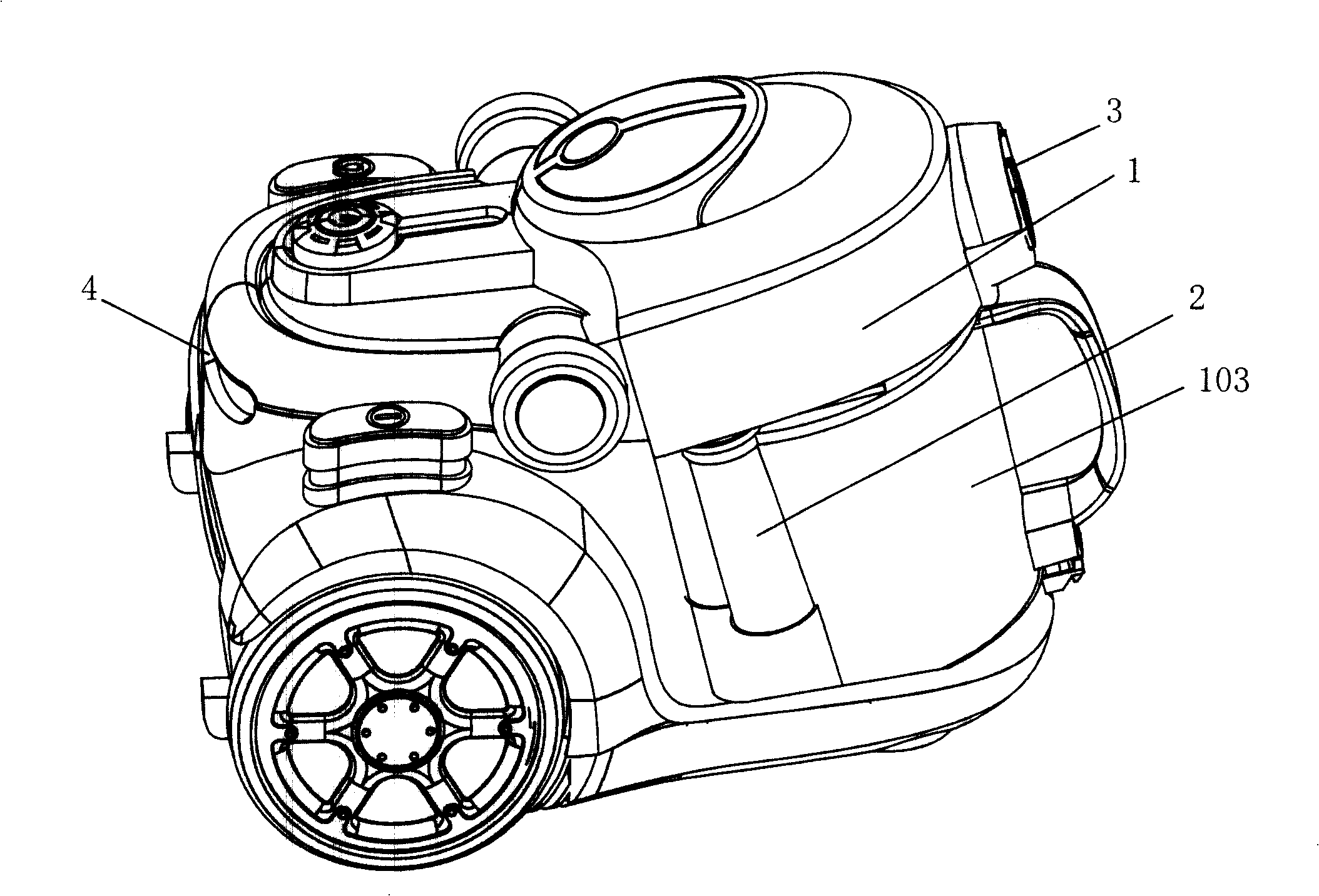
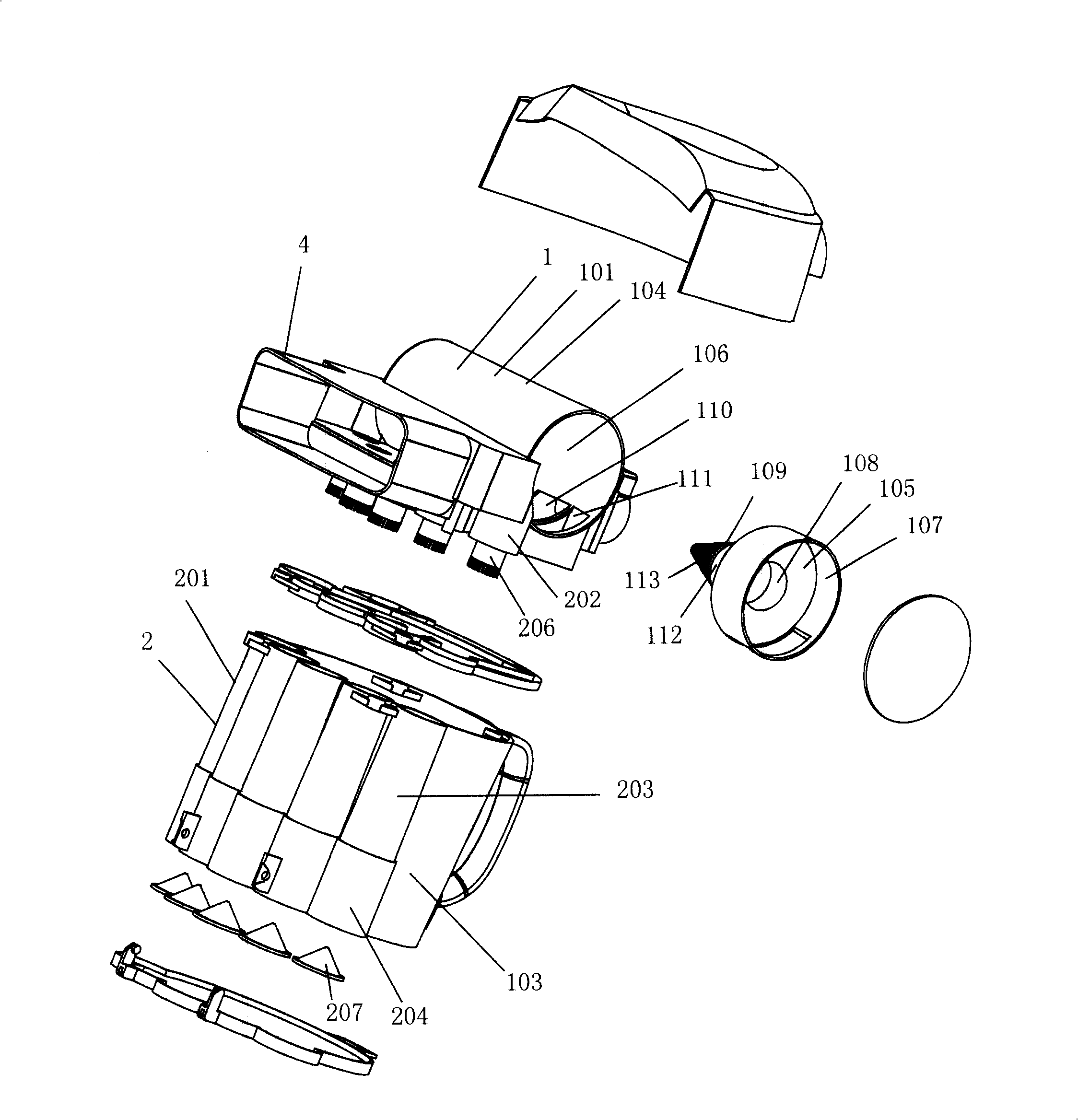
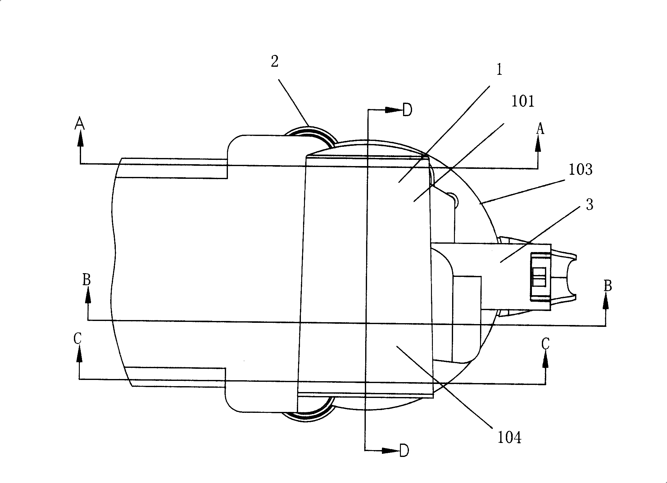
[0030] Example: such as figure 1 , figure 2 , image 3 , Figure 4 , Figure 5 , Figure 6 , Figure 7 , Figure 8 As shown, a dust removal device for a vacuum cleaner includes a primary dust collector 1 and a secondary dust collector 2. The cyclone axis of the primary separation device 101 in the primary dust collector 1 and several of the secondary dust collectors 2 The cyclone axes of the secondary separation device 201 are arranged perpendicular to each other. The primary separation device 101 of the primary dust collector 1 is connected to the dust cup 103 through the dust outlet 102, and the primary separation device 101 is located outside the dust cup 103, and the primary separation device 101 is located outside the dust cup 103. The device 101 is horizontally arranged on the upper part of the dust cup 103, and the secondary separation device 201 is arranged longitudinally on the side of the dust cup 103.

[0031] In the above embodiment, the primary separation device 101 ...


PUM


Abstract

The invention discloses a dust removing plant of a dust collector which comprises a first level dust remover and a second level dust remover. The cyclone axis of a first level separating device in the first level dust remover and the cyclone axis of a second level separating device in the second level dust remover are arranged in a mutual perpendicular way; the first level separating device of the first level dust remover is communicated with a dust cup through a dust outlet and the first level separating device is arranged outside the dust cup; the cyclone axis of the first level dust remover and the cyclone axis of the second level dust remover are arranged in a mutual perpendicular way, thereby avoiding the mutual impact between the dust discharging direction and the wind discharging direction of the first level dust remover and therefore, not only filtration efficiency is promoted, but also that the first level dust remover can be arranged outside the dust cup, thereby increasing dust storing quantity of the dust cup and reducing times of clearing up the dust cup for users.

Description

technical field [0001] The invention relates to a dust removal device of a vacuum cleaner. Background technique [0002] A filter is installed in a traditional vacuum cleaner to filter the inhaled dirty air and keep the dust particles in the dust collection device. Therefore, after using this type of vacuum cleaner for a period of time, the user should clean or replace the filter. Otherwise, the filter holes of the filter will be blocked by fine dust, which will increase the resistance of the vacuum motor, and even burn out the motor in severe cases, which not only brings trouble to the user, but also affects the performance and life of the vacuum cleaner. [0003] In recent years, manufacturers have replaced filters with cyclones based on the principle of cyclone separation, and achieved better dust removal effects, which have been widely applied to vacuum cleaners. The cyclone is provided with an inverted cone-shaped cyclone in the dust cup, and an air outlet pipe is arra...

Claims


Application Information

Patent Timeline
IPC IPC(8): A47L9/16
Inventor 倪祖根
Owner KINGCLEAN ELECTRIC GREEN TECH SUZHOU
Why Eureka
Try Eureka