Hydraulic safety valve

A safety valve and hydraulic technology, applied in the field of hydraulic safety valves, can solve problems such as mechanical troubles

Inactive Publication Date: 2010-12-29
WEISAIER HYDRAULIC
View PDF7 Cites 0 Cited by
  • Summary
  • Abstract
  • Description
  • Claims
  • Application Information

AI Technical Summary

Problems solved by technology

But the mechanism used for this is cumbersome

Method used


Image

  • Hydraulic safety valve
  • Hydraulic safety valve

Examples


Embodiment Construction

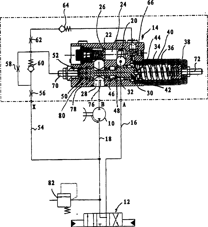
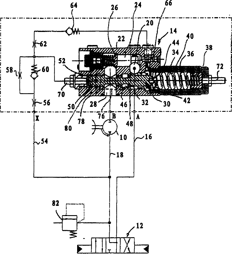
[0012] In the drawing, a hydraulic motor 10 is provided at 10 , which, for example, lifts a load not shown in detail. The motor 10 is controlled by a controller 12, for example a three-position valve, which is electromagnetically actuated. The pump supplying the motor 10 with oil and the associated oil tank are not shown. A safety valve 14 is provided between the controller 12 and the motor 10 . An up line 16 and a down line 18 are located between the safety valve 14 and the controller 12 . The ascending line 16 opens at 20 into a housing 22 of the valve 14 . A spring-loaded check valve 26 is provided, connecting the inlet 20 to a passage 24 . The non-return valve normally closes off a passage 28 to the hydraulic motor 10 .

[0013] A spool 30 is movably disposed in the axial bore of the housing 22 . It has a valve section 32 which cooperates in a sealing manner with an associated sealing edge in the bore of the housing 22 when it is pressed into the closed position by me...


PUM


Abstract

A hydraulic relief valve comprises a valve housing; a passage which makes a hydraulic driving device to be connected directly with a controller in the housing; a check valve which opens toward the hydraulic driving device in the passage; a control slide valve; and a regulator section. wherein the passage is connected with a connector of the controller side and a connector of the drive side; the control slide valve is provided with a valve section which releases a connection positioned between the connector of the drive side and the connector of the controller side which jumpers over the checkvalve and parallels with the passage at an opening position of the valve section, the valve section is adjusted by a spring in a closing direction but to be adjusted by a pre-control piston in an opening direction, wherein, an acting surface of the pre-control piston is loaded to control pressure; the regulator section acts upon together with seamed edges of the housing on the control slide valve, only the valve section opens, the regulator section can release a through flow, wherein, a ring seal in the housing makes the pre-control piston seal relative to the passage. The , hydraulic relief is characterized in that an annular chamber is arranged between the valve section and the regulator section in the housing, and an annular groove is arranged between the ring seal and the passage, andis connected by one passage and the annular chamber.

Description

technical field [0001] The invention relates to a hydraulic safety valve. Background technique [0002] A hydraulic safety valve is known from DE 40 32 420 C2, which has a passage directly connecting a consumer to a controller, on which a non-return valve is arranged. The control spool valve (spool) in the housing has a valve section which is arranged on both sides of the check valve in the connection between the passage sections and which is spring-adjusted in the closing direction and pre-controlled in the opening direction Piston adjustment, on which the control pressure acts on an active surface. There is also a stagnation pressure which acts on the resulting flow which bypasses the non-return valve, for example in the case of a lowering movement of the load, which exerts an influence on the control slide in the closing direction. If this stagnation pressure drops or even falls to zero, for example due to a line break on the controller side, there is the risk of the co...

Claims


Application Information

Patent Timeline
Patent Type & Authority Patents(China)
IPC IPC(8): F15B20/00F16K17/19
Inventor 洛塔尔·米夏埃利斯迪尔克·范比伦哈拉尔德·维斯纳
Owner WEISAIER HYDRAULIC
Why Eureka
Try Eureka