Structure of power supply to be mounted on vehicle

A power supply device and vehicle technology, which is applied to the arrangement of multiple different prime movers of electric power devices and general power devices, power devices, etc. big problem

Inactive Publication Date: 2008-09-10
TOYOTA JIDOSHA KK
View PDF3 Cites 7 Cited by
  • Summary
  • Abstract
  • Description
  • Claims
  • Application Information

AI Technical Summary

Problems solved by technology

This structure leads to an increase in the overall length of the power supply unit, thereby causing constraints on the process of mounting the power supply unit in the vehicle
Specifically, in the case of installing the power supply unit such that its long side extends in the vehicle width direction or installing the power supply unit at the front and rear of the vehicle, it is difficult to secure the contact between the power supply unit and the vehicle body in view of a collision of the vehicle. gap

Method used


Image

  • Structure of power supply to be mounted on vehicle
  • Structure of power supply to be mounted on vehicle
  • Structure of power supply to be mounted on vehicle

Examples


no. 1 example

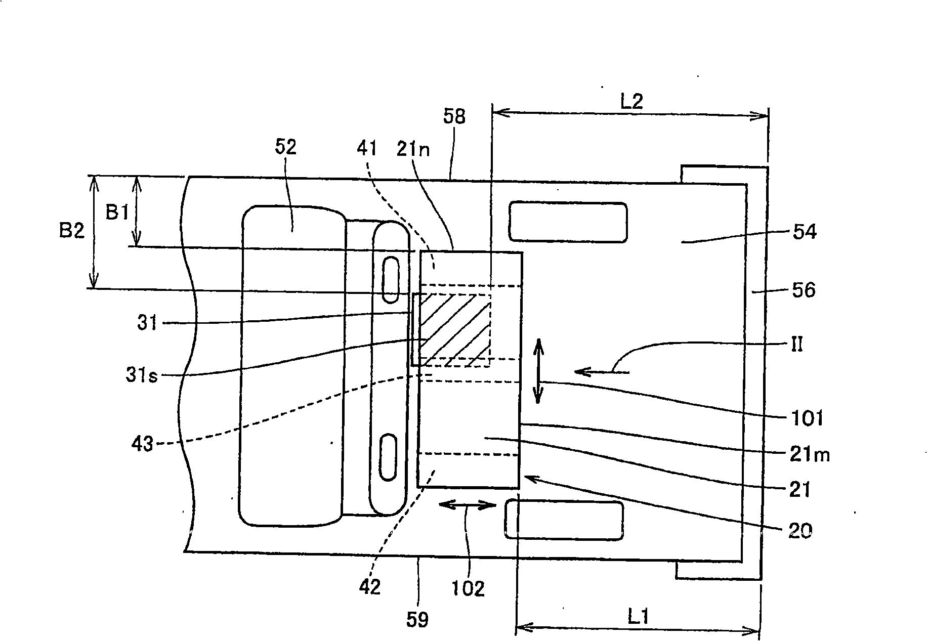
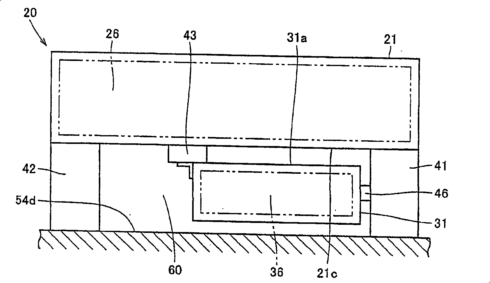
[0025] figure 1 is a plan view of a hybrid vehicle to which the structure for mounting a battery pack in the vehicle according to the first embodiment of the present invention is applied, showing the rear of the hybrid vehicle. figure 2 From figure 1 The rear view of the battery pack viewed in the direction indicated by the arrow II.

[0026] refer to figure 1 and figure 2 , the hybrid vehicle shown in the figure uses an internal combustion engine such as a gasoline engine and a diesel engine, and an electric motor receiving electric power from a chargeable and dischargeable battery device 26 as power sources.

[0027] The rear seat 52 is arranged inside the hybrid vehicle. Behind the rear seat 52, a trunk 54 is provided as a space for loading luggage. The battery pack 20 is installed on the floor surface 54d of the trunk 54 . The battery pack 20 is arranged at a position relatively closer to the rear seat 52 provided between the rear seat 52 and the rear bumper 56 at ...

no. 2 example

[0058] Figure 7 is a plan view of a hybrid vehicle to which the structure for mounting the battery pack in the vehicle according to the second embodiment of the present invention is applied. Compared with the structure for installing the battery pack 20 in the vehicle in the first embodiment, the structure for installing the battery pack in the vehicle has substantially the same structure in the present embodiment. A description of the same structure will not be repeated.

[0059] refer to Figure 7, in the present embodiment, the battery pack 20 is arranged below the driver's seat 50 and the passenger seat 51 arranged inside the vehicle. Similar to the first embodiment, battery case 21 is arranged such that its relatively long sides extend in the width direction of the vehicle and its relatively short sides extend in the longitudinal direction of the vehicle. The battery case 21 and the auxiliary mechanism case 31 are arranged one on top of the other such that the auxilia...


PUM


Abstract

A structure for mounting a battery pack device (20) on a vehicle has assembled battery cells mounted on the vehicle, accessories electrically connected to the assembled battery cells and using the cells, a battery case (21) for receiving the assembled battery cells, and an accessory case (31) for receiving the accessories. The battery case (21) and the accessory case (31) are arranged such that that portion (31s) of the accessory case (31) which is projected in the vertical direction is superposed on the battery case (21). The structure has excellent mountability.

Description

technical field [0001] The present invention generally relates to a structure for mounting a power supply device in a vehicle, and more particularly to a structure for mounting a power supply device in a vehicle provided with an auxiliary mechanism for using a power source. Background technique [0002] As for a conventional structure for mounting a power supply device in a vehicle, for example, Japanese Patent Laid-Open Publication No. 2005-153827 discloses an on-vehicle power storage device that aims to reduce the number of parts and the number of manufacturing processes. The vehicle-mounted power storage device disclosed in this document includes a battery as a direct current (DC) power source, and a battery protection unit in which a main switch, a main fuse, a battery current sensor for detecting an overcurrent, and a cut-off The interrupter of the output circuit of the storage battery, etc. The battery and the battery protection unit are arranged in a straight line in...

Claims


Application Information

Patent Timeline
Patent Type & Authority Applications(China)
IPC IPC(8): B60K1/04B60K6/28B60L15/00B60K6/40
CPCB60K1/04B60K2001/0438B60K6/48Y02T10/6221Y02T10/62
Inventor 永田修一
Owner TOYOTA JIDOSHA KK
Why Eureka
Try Eureka