
Laser used vibration measurement device and its adjustment method

A technology for laser vibration measurement and equipment, which is applied to measurement devices, ultrasonic/sonic/infrasonic waves, instruments, etc., and can solve the problems of fixed working distance of vibration measurement equipment, increased manufacturing cost of vibration measurement instruments, and larger volume of vibration measurement instruments. , to achieve the effect of reducing the amount of manual operations, easy and convenient installation, reducing volume and weight

Inactive Publication Date: 2017-02-15
NINGBO SUNNY INTELLIGENT TECH CO LTD +1
View PDF7 Cites 0 Cited by
  • Summary
  • Abstract
  • Description
  • Claims
  • Application Information

AI Technical Summary

Problems solved by technology

After using a large-sized lens, the volume and weight of the entire vibrometer will increase, and it will also increase the manufacturing cost of the vibrometer itself
[0008] Aiming at the problems of fixed working distance, large volume and weight, and high cost of vibration measuring equipment in the prior art, no effective solution has been proposed so far

Method used


Image

  • Laser used vibration measurement device and its adjustment method
  • Laser used vibration measurement device and its adjustment method
  • Laser used vibration measurement device and its adjustment method

Examples


Embodiment Construction

[0064] The description of this illustrative embodiment should be combined with the corresponding drawings, which should be taken as a part of the complete specification. In the drawings, the shape or thickness of the embodiments can be enlarged, and are marked for simplicity or convenience. Furthermore, the structural parts in the drawings will be described separately. It is worth noting that the elements that are not shown in the drawings or are not described by text are in the form known to those of ordinary skill in the art.

[0065] In the embodiments described below, the technical features in these embodiments will be described separately. These features may exist independently or in combination, and the present invention is not particularly limited to the preferred embodiments. The scope of the present invention is defined by the claims.

[0066] According to an embodiment of the present invention, a laser vibration measuring device is provided.

[0067] Such as figure 1 with...


PUM


Abstract

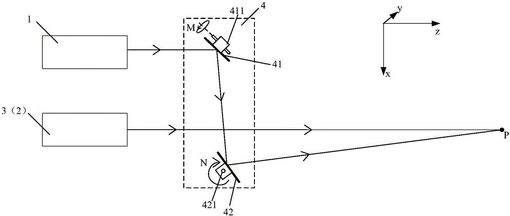
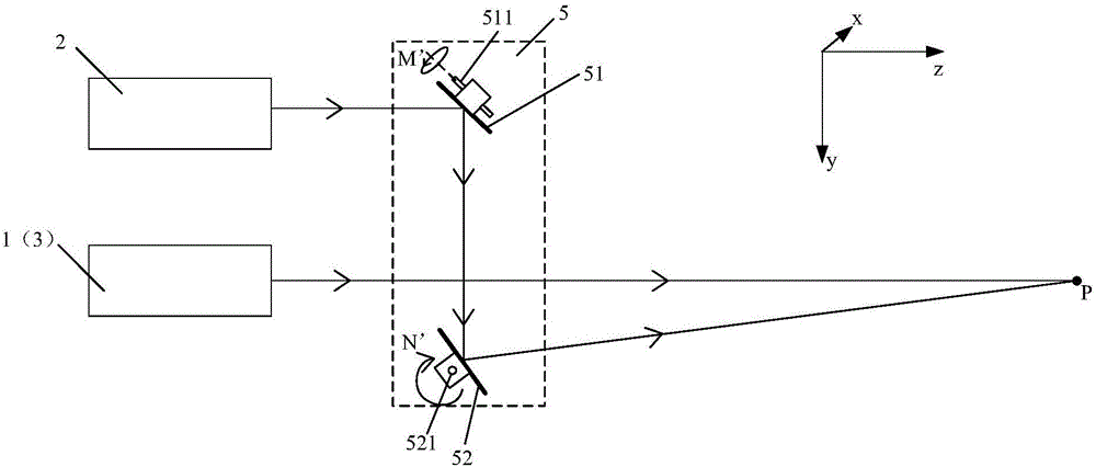
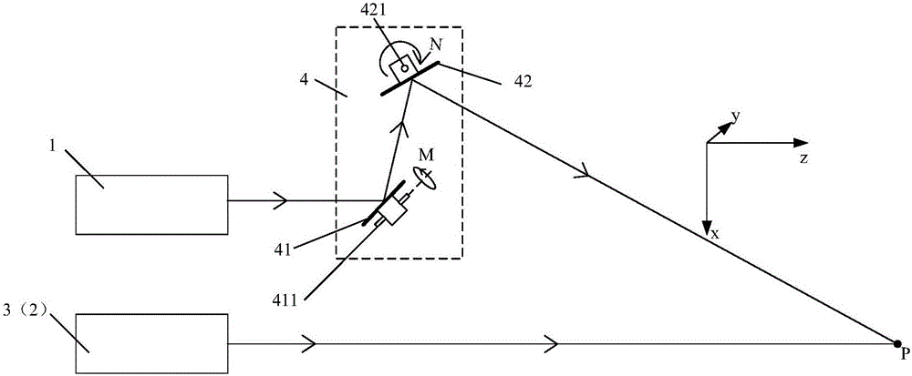
The invention discloses a laser used vibration measurement device and its adjustment method wherein the device comprises a first laser, a second laser, a third laser, a first reflection mechanism and a second reflection mechanism. The first reflection mechanism is mounted at the emitting light path of the first laser; and the first reflection mechanism is used to change the light path of the light from the first laser. The second reflection mechanism is mounted at the emitting light path of the second laser; and the second reflection mechanism is used to change the light path of the light from the second laser. The emitting light from the first reflection mechanism and the second reflection mechanism converges with the emitting light from the third laser. The first reflection mechanism and the second reflection mechanism both consist of an optical lens assembly and a driving mechanism wherein the driving mechanism is used to drive the optical lenses in the optical lens assembly to move to change the direction of the emitting light. According to the invention, it is possible to change the working distance of a laser used vibration measurement device simply and effectively. In addition, the size and weight of the laser used vibration measurement device can be reduced; the cost can be too. Therefore, the manufacturing of such device become easier.

Description

Technical field [0001] The invention relates to the field of laser measurement, and in particular, to a laser vibration measurement equipment and an adjustment method thereof. Background technique [0002] Vibration widely exists in various fields such as life, industrial production, and scientific research. In these fields, there is a great demand for vibration measurement. The measurement of vibration is divided into contact measurement and non-contact measurement. Among them, non-contact measurement will not affect the original state of vibration, and the measurement results are more accurate and reliable, and it has become the development direction of vibration measurement. [0003] At present, the more mature non-contact vibration measurement technology is laser Doppler technology, which generally adopts a heterodyne structure. Laser vibration measurement has many advantages such as non-contact, high accuracy, and easy installation. It has been widely used in material flaw ...

Claims


Application Information

Patent Timeline
IPC IPC(8): G01H9/00
CPCG01H9/00
Inventor 宋耀东杨兴刘志方宋云峰
Owner NINGBO SUNNY INTELLIGENT TECH CO LTD
Learn More