Cooking fume purifier

A technology of oil fume purification and oil fume purifier, which is applied in the direction of chemical instruments and methods, dispersed particle separation, separation methods, etc., to achieve the effect of eliminating pollution and quickly absorbing oil fume

Inactive Publication Date: 2008-09-17
王君
View PDF0 Cites 3 Cited by
  • Summary
  • Abstract
  • Description
  • Claims
  • Application Information

AI Technical Summary

Problems solved by technology

In addition, the flue that is generally equipped in buildings is the main channel for concentrated emission of oil fume, but due to the accumulation of smoke oil in the flue for many years, it has become one of the hidden dangers of fire.

Method used


Image

  • Cooking fume purifier
  • Cooking fume purifier
  • Cooking fume purifier

Examples


Embodiment 1

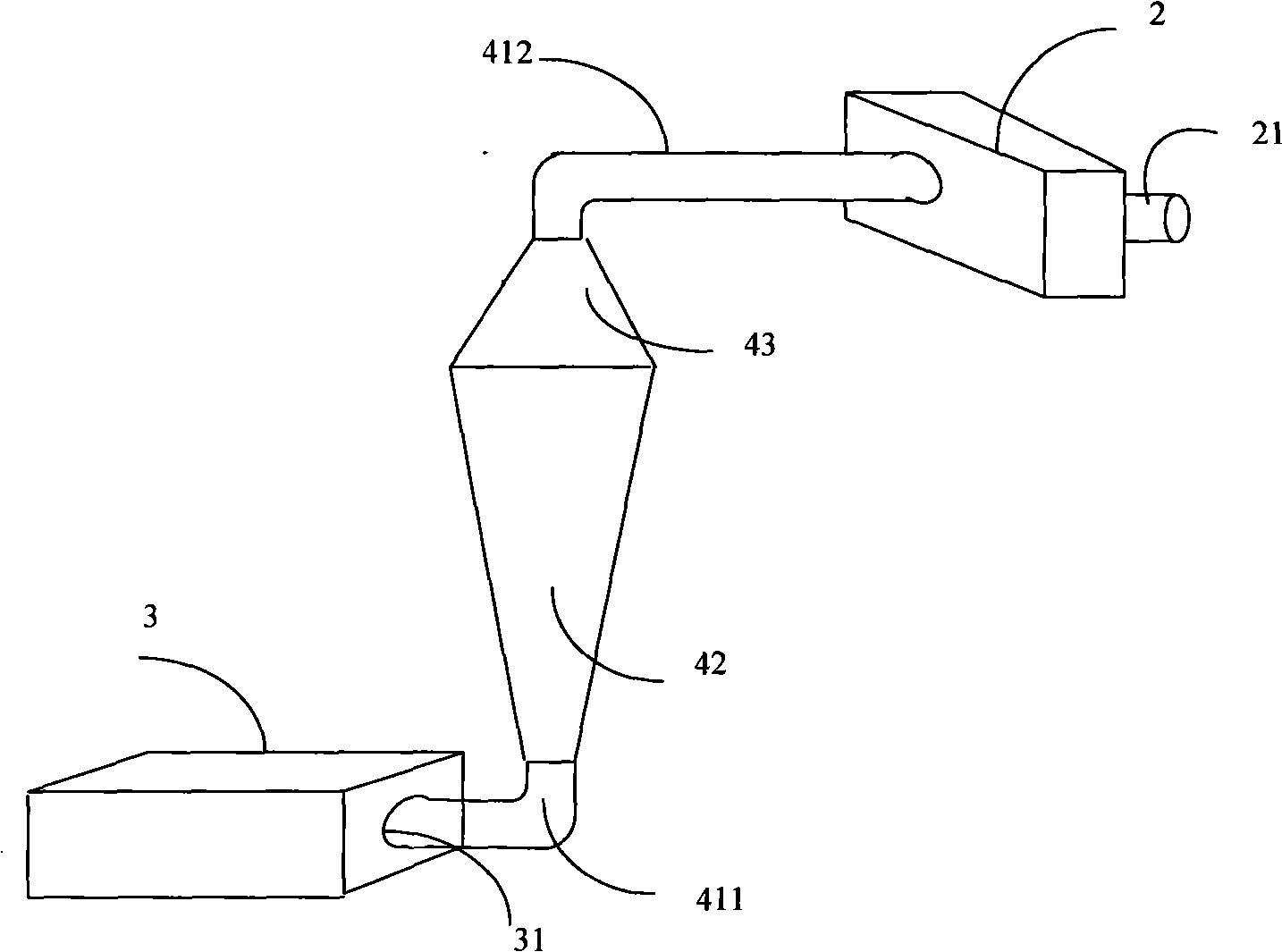
[0042] Such as figure 1 As shown, this embodiment includes a blower fan 2, which is used to generate power for sucking oil fume gas. It also includes a box-shaped oil fume collector 3, which is responsible for collecting the oil fume gas. The oil fume collector 3 is provided with an air intake hole 31, and the air intake hole 31 is connected with the air intake pipe 411 provided on the oil fume purifier. The oil fume purifier includes a conical cyclone pipe 42 , and one end of the cyclone pipe 42 with a larger diameter is buckled with a conical outlet air cover 43 . The air outlet pipe 412 is arranged on the top of the outlet air cover 43 and communicates with the inside of the outlet air cover 43 . The fan 2 is provided with an air outlet 21 .

[0043] When this embodiment is working, under the action of the blower fan 2, the end of the whirlwind pipe 42 with a smaller diameter is the suction port for the fume gas collected by the fume collector. The tube wall of the cycl...

Embodiment 2

[0052] The structure of the second embodiment of the present invention is basically the same as the first embodiment, and its difference with the first embodiment is that the technical feature of the first embodiment is to utilize the centrifugal action of high-speed rotation to clean the air, and the second embodiment The technical feature is to use activated carbon and molecularly modified paint to filter and purify the peculiar smell of oil fume. Therefore, except for the differences in the internal structure of the cyclone tube 42 in the second embodiment, other points that are the same as those in the first embodiment will not be illustrated.

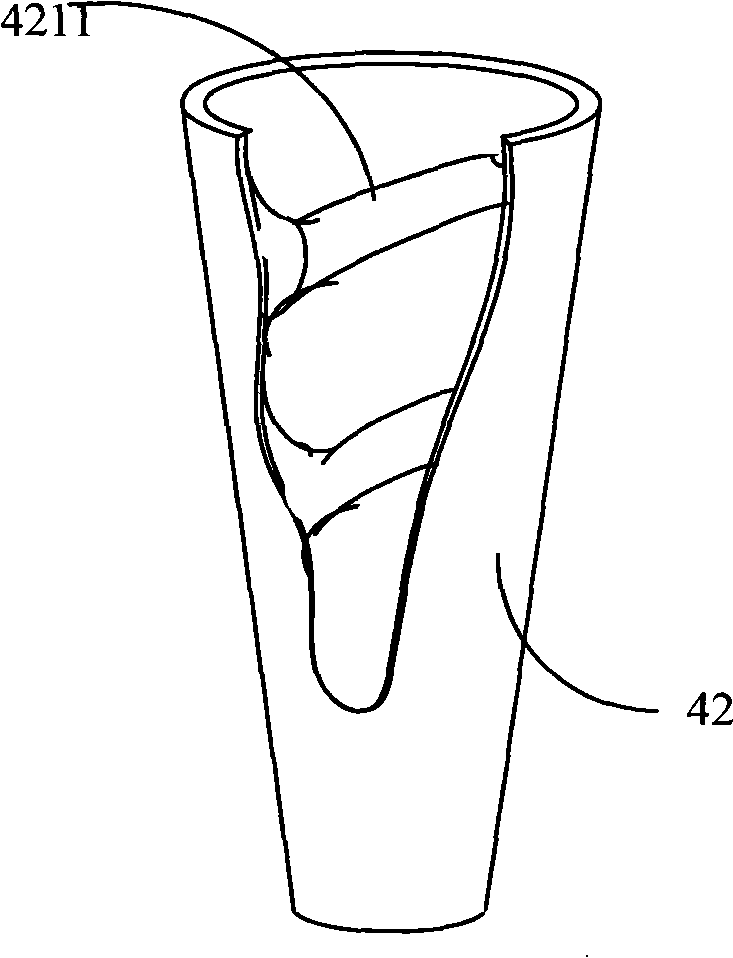
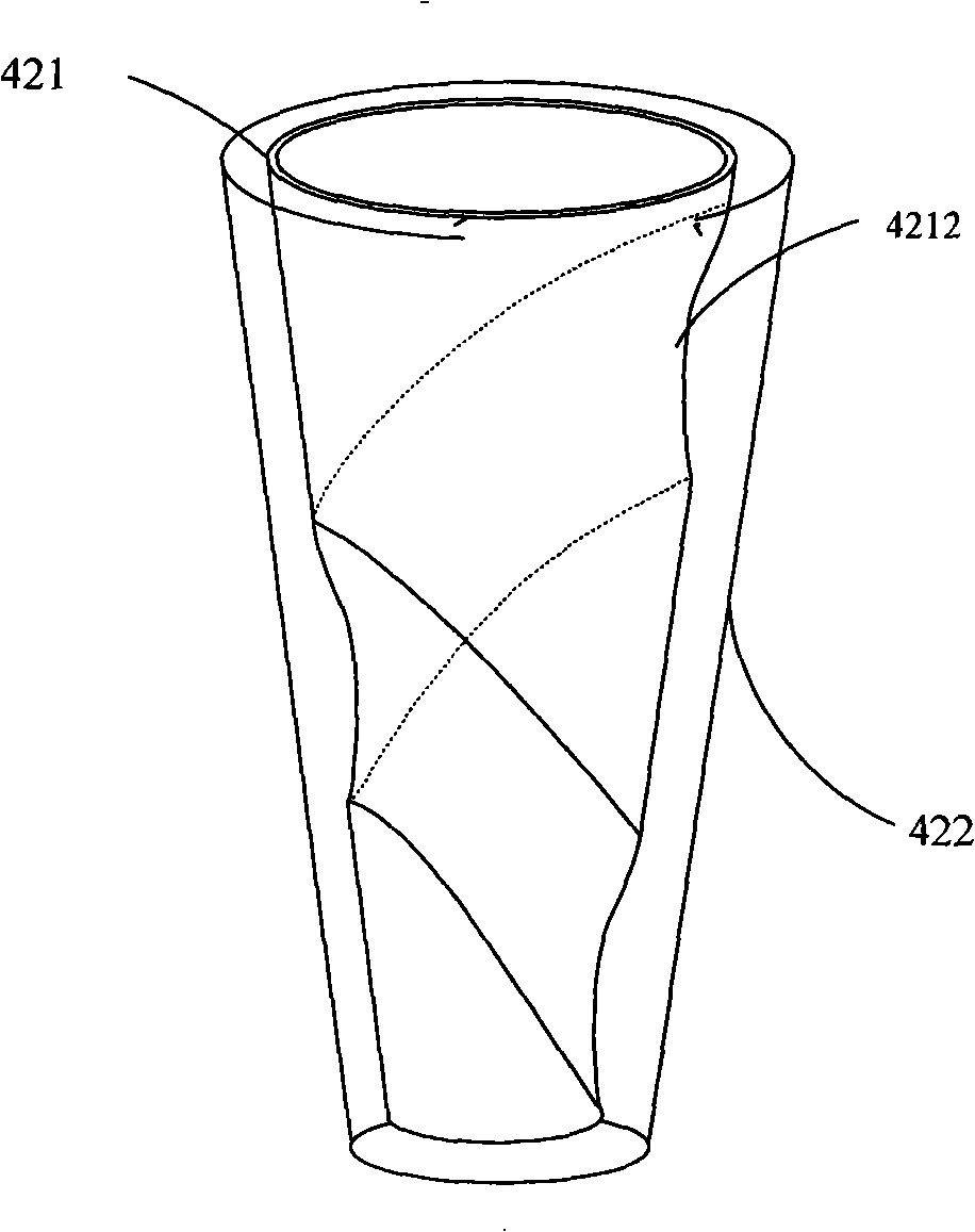
[0053] Such as Figure 7 As shown, in the second embodiment, the inner wall layer 421 and the outer wall layer 422 of the cyclone pipe 42 do not directly pass through the opening at the end with a larger diameter, and the inner wall layer and the outer wall layer are isolated so that they pass through the filter screen Only then c...

Embodiment 3

[0059] Such as Figure 10 As shown, this embodiment includes an axial flow fan 2 arranged in the cabinet 1, and the axial flow fan 2 is used for sucking oil fume gas. A box-shaped fume collector 3 is also provided below the cabinet 1 . The oil fume collector 3 is provided with a plurality of air intake holes 31 , and each air intake hole 31 is connected with an air pipe 411 on a oil fume purifier 4 . The oil fume purifier 4 includes a conical cyclone tube 42 , and one end of the cyclone tube 42 with a larger diameter is buckled with a frustum-shaped outlet gas cover 43 . The air pipe (outlet pipe) 412 is arranged on the top of the outlet air cover 43 and communicates with the inside of the outlet air cover 43 . In order to connect the outlet pipes 412 of multiple oil fume purifiers to the fan, a large-diameter confluence air pipe 413 is provided, on which a plurality of air inlets 22 are opened, and the air is discharged from the outlet 21 provided on the chassis 1 through t...


PUM


Abstract

The invention relates to a purification device of oil fume, comprising a fan used for producing gas momentum of oil fume suction, an oil fume collector, an oil and smoke cleaner and a windpipe. The oil and smoke cleaner is connected with the fan by the windpipe; air inlet holes are arranged on the oil fume collector, and the air inlet holes are connected with the oil and smoke cleaner by the windpipe. The oil and smoke cleaner comprises a conical cyclone tube, and an outlet gas hood is buckled at the bigger diameter end of the cyclone tube; an air outlet is arranged at the top part of the outlet gas hood, and is connected with the fan by the windpipe. The invention has the advantages of purifying the oil fume air by the centrifugal function produced by the high-speed cyclone, meanwhile filtering and eliminating peculiar smell, forming a bigger air negative pressure zone while used in series connection and parallel connection, rapidly purifying oil fume gas in large area, and achieving the purifying emission of the oil fume gas. The invention belongs to the environment-friendly technology.

Description

technical field [0001] The invention relates to an oil fume purification device, in particular to an oil fume purification device for separating oil and removing peculiar smell from the oil fume in a cooking room. Background technique [0002] Now, range hoods of various structures are widely used in people's daily life as a kind of kitchen fume equipment. It provides people with a way to discharge the cooking fumes from the kitchen to the outside. However, the existing range hoods still have some technical defects. The more prominent problem is that the current range hoods basically do not consider the purification of the fumes. It is directly discharged, and there are many disadvantages in this in-line method. [0003] The direct discharge of lampblack not only damages the air in the living environment, but also causes social and other problems. For example, the direct rows of concentrated residences such as apartments have a direct impact on the air of neighboring resid...

Claims


Application Information

Patent Timeline
Patent Type & Authority Applications(China)
IPC IPC(8): B01D45/16
Inventor 王君
Owner 王君
Why Eureka
Try Eureka