Elevator apparatus

A technology of elevators and braking devices, which is applied in transportation, packaging, elevators, etc., and can solve problems such as passenger discomfort and increased braking distance

Active Publication Date: 2008-09-17
MITSUBISHI ELECTRIC CORP
View PDF1 Cites 7 Cited by
  • Summary
  • Abstract
  • Description
  • Claims
  • Application Information

AI Technical Summary

Problems solved by technology

[0004] In the conventional braking device as mentioned above, the basic emergency braking action and the braking force control action are both performed by a single braking control unit, so the failure of the braking co

Method used


Image

  • Elevator apparatus
  • Elevator apparatus
  • Elevator apparatus

Examples


no. 1 Embodiment approach

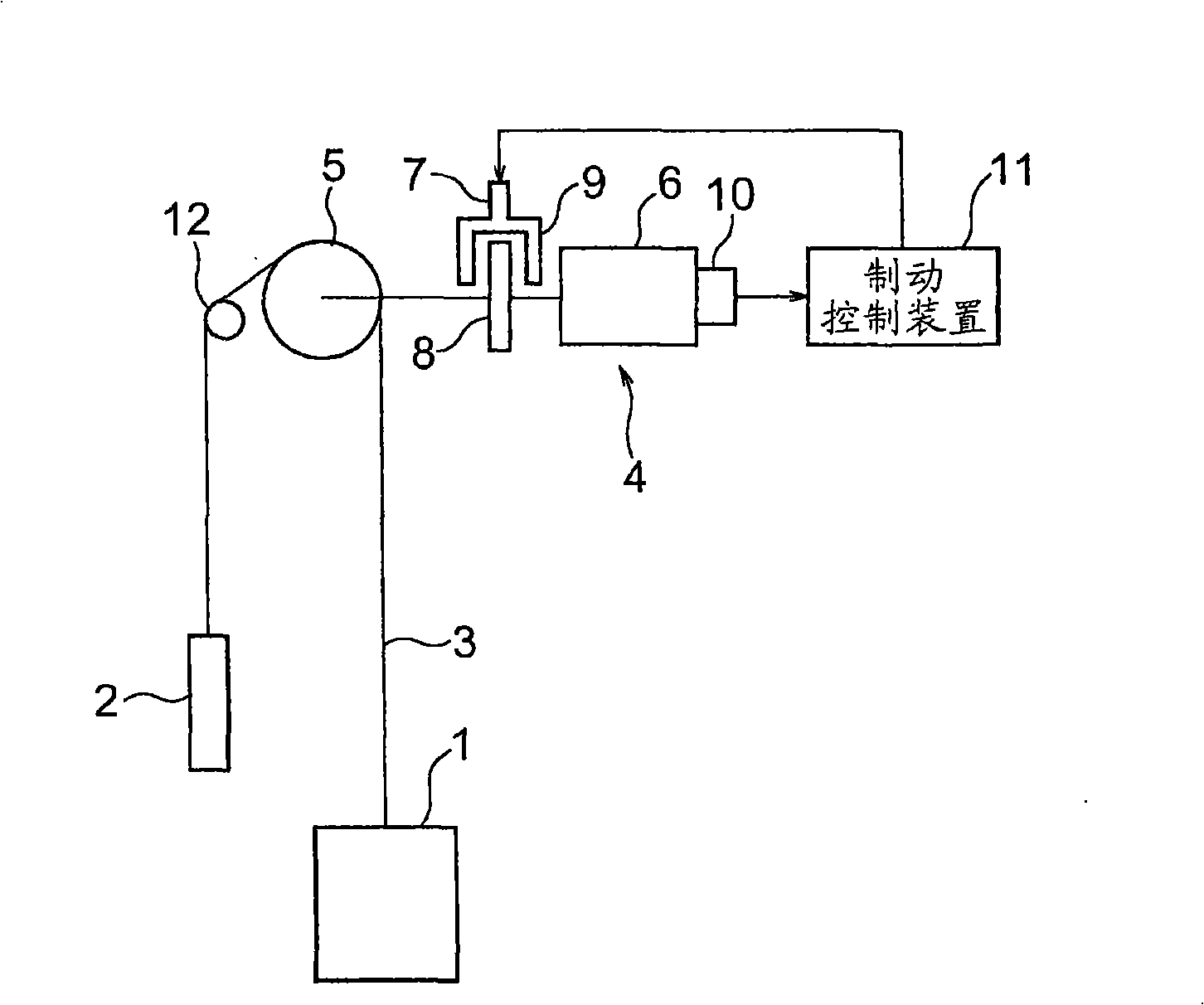
[0018] figure 1 It is a configuration diagram showing the elevator apparatus according to the first embodiment of the present invention. In the figure, the car 1 and the counterweight 2 are suspended in the hoistway by the main rope (suspension unit) 3, and are raised and lowered in the hoistway by the driving force of the hoist 4. The hoist 4 has a drive pulley 5 around which the main rope 3 is wound, a motor 6 that rotates the drive pulley 5 , and a brake unit 7 that brakes the rotation of the drive pulley 5 .

[0019] The brake unit 7 has a brake gear 8 that rotates integrally with the drive pulley 5 , and a brake device 9 that brakes the rotation of the brake gear 8 . The driving pulley 5, the motor 6 and the braking gear 8 are coaxially arranged. The brake device 9 has: a brake shoe (brake shoe), which contacts / separates from the brake gear 8; a brake spring, which presses the brake shoe against the brake gear; and an electromagnet, which overcomes the force of the brak...


PUM


Abstract

In an elevator device, a brake control device has a first brake control section that, when an abnormality is detected, activates a brake device to emergency stop an elevator car and also has a second brake control device that, when the deceleration of the car is not less than a predetermined level when the first brake control section causes emergency braking operation to activate, reduces braking force of the brake device. The second brake control section detects, independent of the first brake control section, the activation of emergency braking by the brake device.

Description

technical field [0001] The present invention relates to an elevator apparatus having a brake control device capable of controlling deceleration of a car during emergency braking. Background technique [0002] In the existing elevator braking device, during emergency braking, the braking force of the electromagnetic brake is controlled according to the deceleration command value and the speed signal, so that the deceleration of the car becomes a predetermined value (for example, refer to Patent Document 1). [0003] Patent Document 1: Japanese Patent Application Laid-Open No. 7-157211 [0004] In the conventional braking device as mentioned above, the basic emergency braking action and the braking force control action are both performed by a single braking control unit, so the failure of the braking control unit may cause the car When the deceleration of the car is too large, it will bring discomfort to the passengers. On the contrary, when the deceleration of the car is too...

Claims


Application Information

Patent Timeline
IPC IPC(8): B66B1/32B66B5/02
CPCB66B1/32B66B5/02
Inventor 上田隆美近藤力雄木川弘
Owner MITSUBISHI ELECTRIC CORP
Why Eureka
Try Eureka