Hollow tire body for cast-in-situ concrete filling

A technology of hollow carcass and cast-in-place concrete, which is applied to floors, building materials, building components, etc., and can solve problems such as low production efficiency, inconvenient assembly line production, and inconvenient production

Inactive Publication Date: 2008-09-24
邱则有
View PDF2 Cites 3 Cited by
  • Summary
  • Abstract
  • Description
  • Claims
  • Application Information

AI Technical Summary

Problems solved by technology

However, this kind of building components is inconvenient to manufacture, the production efficiency is low, it is not convenient for assembly line production, and the corresponding cost is high

Method used


Image

  • Hollow tire body for cast-in-situ concrete filling
  • Hollow tire body for cast-in-situ concrete filling
  • Hollow tire body for cast-in-situ concrete filling

Examples


Embodiment Construction

[0071] The present invention will be further described below in conjunction with the accompanying drawings and embodiments.

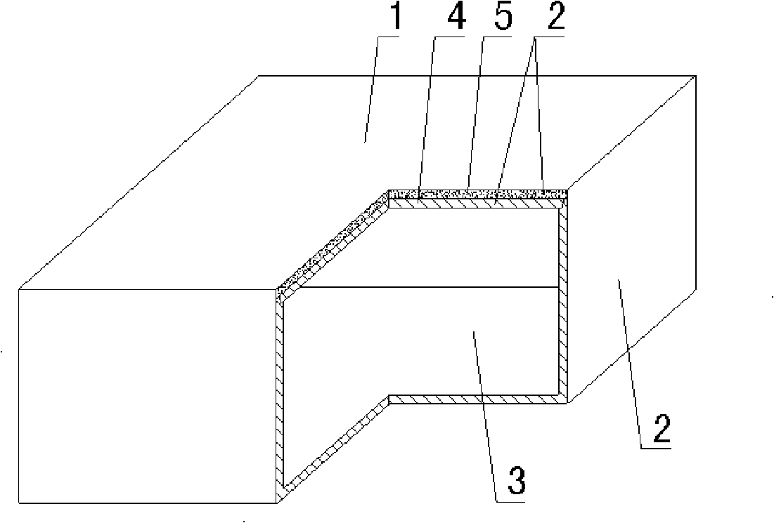
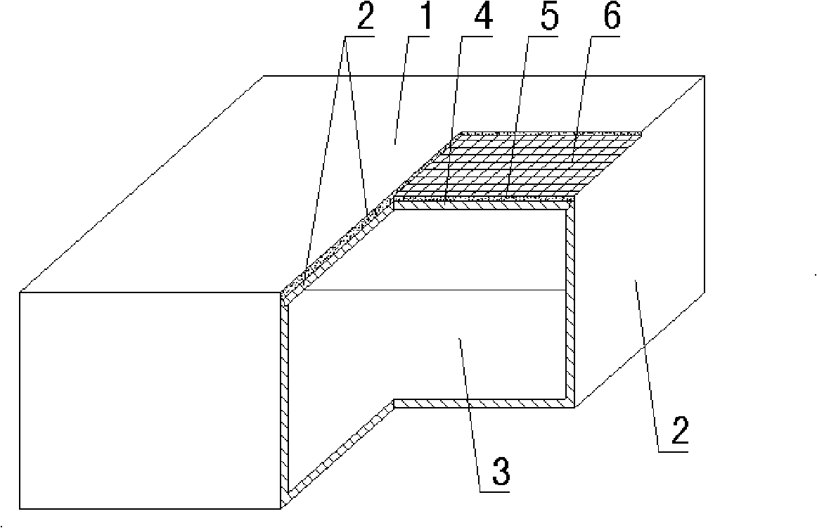
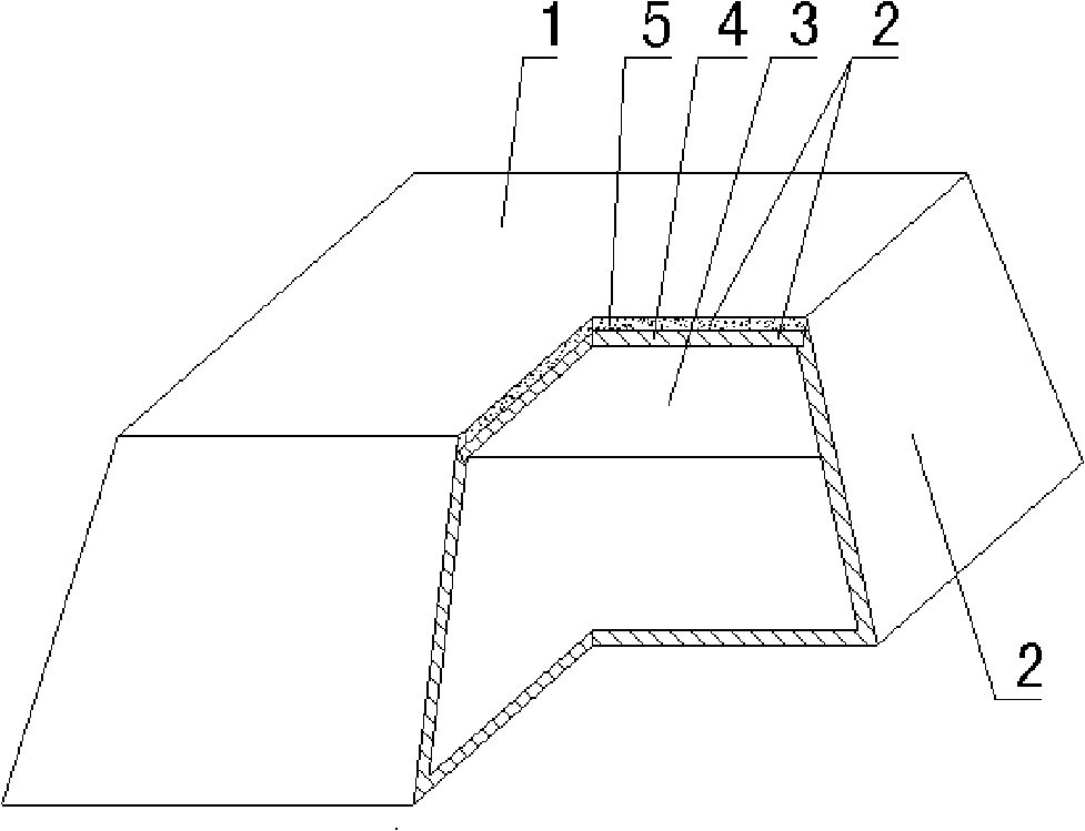
[0072]As shown in the accompanying drawings, the present invention includes a hollow carcass 1, which is formed by surrounding an outer wall 2 and has a cavity 3 inside, and is characterized in that at least one outer wall 2 of the hollow carcass 1 is prefabricated The board wall 4 and the slurry embryo body 5 are made of soft and hard laminated and cemented, and the prefabricated board wall 4 and the slurry embryo body 5 are laminated and solidified with the inner hard and outer soft, and there is a hollow rod for strengthening the upper and lower outer walls. The two ports of the rod communicate with the exterior of the upper and lower outer walls 2 to form a connected hole 17 . In the accompanying drawings, 1 is the hollow carcass, 2 is the outer wall, 3 is the cavity, 4 is the prefabricated board wall, and 5 is the slurry body. In the following draw...


PUM


Abstract

A hollow matrix used for cast-in-place filling includes a hollow matrix (1); the hollow matrix (1) is formed by being surrounded by an outer wall(2); the inside of the hollow matrix (1) is an empty cavity (3); the invention is characterized in that at least one outer wall (2) of the hollow matrix (1) is formed by hard and soft superposition cementation solidifying of a precast plate wall (4) and a slurry embryo body (5); the invention is provided with a hollow rod piece reinforcing the outer wall of the upper part and the lower part; the two end openings of the hollow rod piece are communicated with the outside of the outer wall(2) of the upper to form a communicated cavern(17); the invention is suitable for the hollow plates, building covers, roofs, wall bodies, foundation bottom plates of the cast-in-place reinforced concrete or prestressed reinforced concrete as well as bridges, in particular to the using of a hollow beam-free building cover.

Description

[0001] This application is a divisional application of an invention patent application with an application date of August 11, 2004, an application number of 200410155218.0, and a title of "a hollow matrix for filling cast-in-place concrete". (1) Technical field [0002] The invention relates to a hollow matrix for filling cast-in-place concrete. (2) Background technology [0003] At present, the cast-in-place concrete hollow floor is a widely used floor structure. The lightweight permanent tire molds filled in it include various hollow tubes and boxes, and the boxes are hollow or solid. For example, the patent No. ZL99249798.1, which the applicant applied for on November 29, 1999, is a utility model patent named "fiber-reinforced thin-walled member for reinforced concrete filling", which discloses a thin-walled formwork member, including an upper plate, The surrounding side walls, the lower bottom, and the upper plate, the surrounding side walls and the lower bottom form a p...

Claims


Application Information

Patent Timeline
Patent Type & Authority Applications(China)
IPC IPC(8): E04C1/00E04C1/39E04C1/40E04B5/36E04B5/18
Inventor 邱则有
Owner 邱则有
Why Eureka
Try Eureka