
Dust-proof cover device

A dust-proof cover and base technology, which is applied in the direction of optics, instruments, camera bodies, etc., can solve the problems of space occupation, inconvenient assembly, and many components of the dust-proof cover device

Inactive Publication Date: 2011-05-04
ASIA OPTICAL CO INC
View PDF6 Cites 0 Cited by
  • Summary
  • Abstract
  • Description
  • Claims
  • Application Information

AI Technical Summary

Problems solved by technology

[0007] Therefore, the technical problem to be solved by the present invention is to provide a device that uses fewer parts and can be easily assembled and greatly reduces the defects of the dust cover device in the prior art. Small assembly volume, and dust cover assembly to reduce manufacturing costs

Method used


Image

  • Dust-proof cover device
  • Dust-proof cover device
  • Dust-proof cover device

Examples


Embodiment Construction

[0017] The aforementioned and other technical contents, features and functions of the dustproof cover device of the present invention will be clearly understood in the following detailed description of preferred embodiments with reference to the drawings.

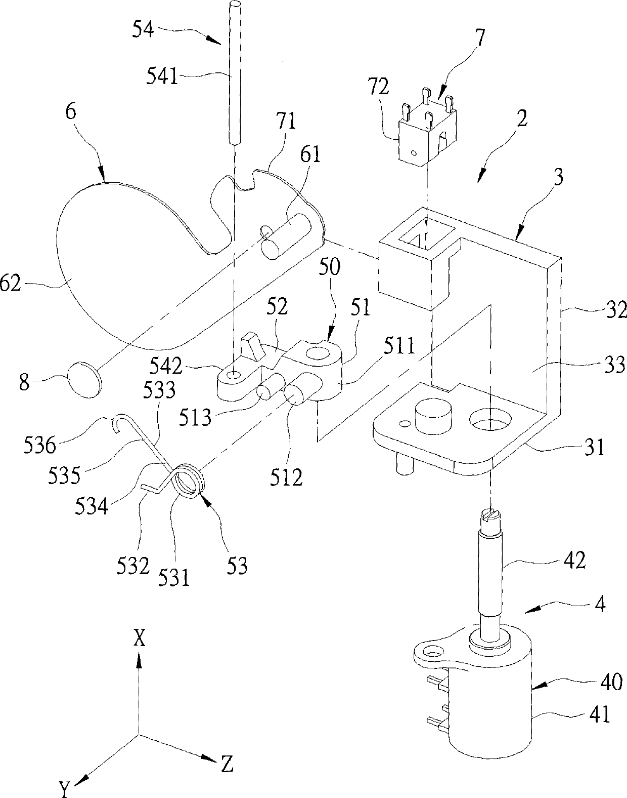
[0018] refer to image 3 and Figure 4 , are the three-dimensional exploded view and the three-dimensional assembly view of the present invention respectively, the preferred embodiment of the dust cover device 2 of the present invention includes a base 3, a drive mechanism 4 mounted on the base 3, connected by the drive mechanism 4 A moving dust cover 6, and a position sensing unit 7 respectively provided on the base 3 and the dust cover 6 correspondingly.

[0019] The base 3 includes a base wall 31 , and a side wall 32 extending from the base wall 31 along a first direction X and cooperating with the base wall 31 to define a receiving space 33 .

[0020] The driving mechanism 4 includes a power unit 40 and a transmission ...


PUM


Abstract

The invention relates to a dustproof cover device which comprises a pedestal, a power unit, a transmission unit and a dustproof cover. The power unit comprises a motor and a lead screw under the bidirectional driving of the motor. The transmission unit comprises a slide base for mounting the lead screw, two resisting parts arranged at the slide base and a guide combination body which ensures thatthe slide base traverses. The dustproof cover comprises a linkage part contained and arranged between the two resisting parts and a cover plate part which is connected with the linkage part. The leadscrew is driven to drive the slide base to move, and the two resisting parts can be used for resisting the linkage part, so as to open and close the dustproof cover, which ensures that the assembly components of the invention are few and can be assembled conveniently to reduce the assembly cubage and reduce the manufacturing cost.

Description

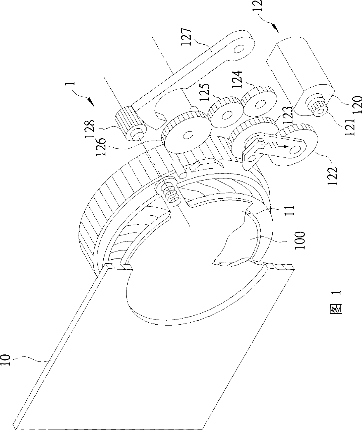
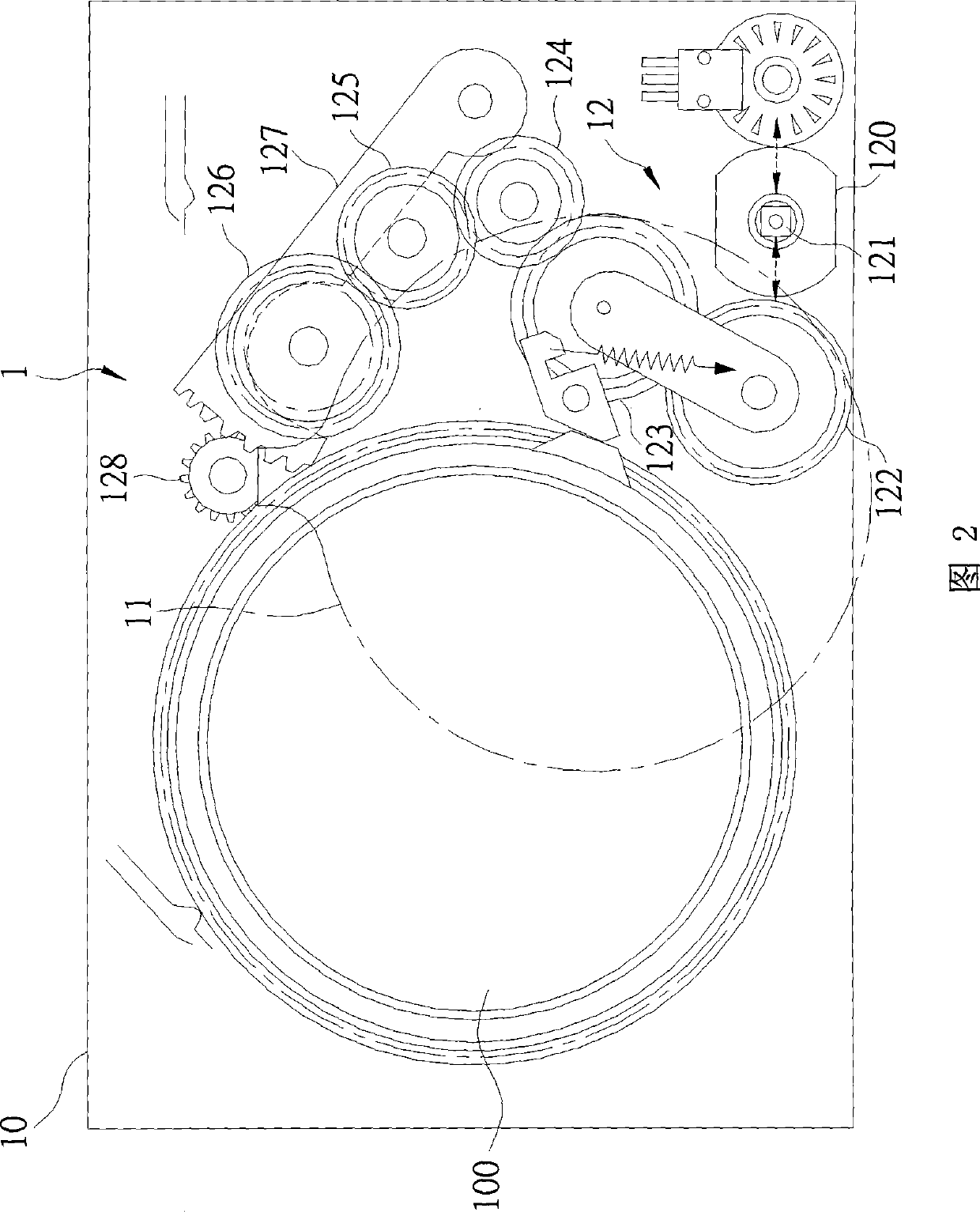
technical field [0001] The invention relates to an optical device, in particular to a dust-proof cover device suitable for imaging devices such as cameras, video cameras, or projectors to protect their lenses. Background technique [0002] Referring to Fig. 1 and Fig. 2, a dust cover device 1 among the US Pat. The dust cover 11, and a drive unit 12 for moving the dust cover 11 relative to the lens 100 between an open position and a closed position. [0003] The driving unit 12 has a motor 120, a power gear 121 coaxial with the motor 120 and bidirectionally driven by it, a first gear 122 meshed in sequence, a second gear 123, a third gear 124, A fourth gear 125 , a fifth gear 126 , a gear rack 127 pushed by the fifth gear 126 , and a sixth gear 128 meshed with the gear rack 127 and connected to the dustproof cover 11 . [0004] When the dust cover 11 is to be moved relative to the lens 100, the motor 120 is first activated to drive the power gear 121 to rotate, and then ind...

Claims


Application Information

Patent Timeline
Patent Type & Authority Patents(China)
IPC IPC(8): G03B17/04
Inventor 薛春育黄敦揆
Owner ASIA OPTICAL CO INC
Learn More