

Low tension coil of transformer with split windings
A technology for splitting transformers and low-voltage coils, which is applied to transformer/inductor coils/windings/connections, coil manufacturing, etc. Superior capability, good capacitance distribution, and increased safety effects
Inactive Publication Date: 2008-09-24
XD JINAN TRANSFORMER
View PDF0 Cites 2 Cited by
- Summary
- Abstract
- Description
- Claims
- Application Information
AI Technical Summary
Problems solved by technology
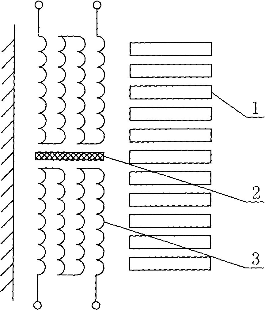
like figure 1 As shown, the low-voltage coil of the current split transformer is a traditional spiral winding, and the terminal outlet is located between the high-voltage and low-voltage coils. The terminal outlet of the low-voltage coil must pass through the main magnetic flux leakage channel, which increases the insulation distance and increases the manufacturing cost. Security risks
Method used
View moreImage
Smart ImageViewing Examples

Examples
Embodiment Construction
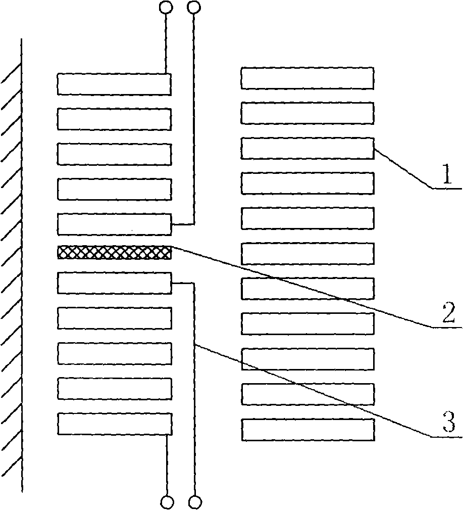
[0009] This specific embodiment has a cylindrical winding structure, and both the head end and the end end of the split transformer lead out from the main flux leakage channel. It is used like figure 2 As shown, there are two low-voltage coils 3 of this specific embodiment arranged side by side on one side of a high-voltage coil 1. The two low-voltage coils 3 are separated by an insulating partition 2. The gap between the two low-voltage coils 3 and the high-voltage coil 1 forms the main drain. In the magnetic air channel, the first ends and the ends of the two low-voltage coils 3 all go out from the outside of the main magnetic leakage air channel.
Login to View More PUM
 Abstract
The invention discloses a low voltage coil of a split transformer. The low voltage coil is a cylinder winding-typed structure and wires of the head and the tail of the low voltage coil pass through the exterior of the main magnetic leakage hollow passage of the split transformer. The low voltage coil adopts the cylinder-typed winding which can be made of normal wires or transposition wires. The outlet wire at the end of the low voltage coil is not necessary to pass through the main magnetic leakage hollow passage, thus improving safety; furthermore, the capacitor distribution of the winding is extremely good and has outstanding capability of impact voltage resistance, and the cost can be effectively reduced by the low voltage split transformer.
Description
(1) Technical field [0001] The invention relates to a low-voltage coil, in particular to a low-voltage coil of a split transformer. (2) Background technology [0002] Split transformers are generally used in power plants as start-up backup transformers, where the low-voltage coil voltage is low and the current is large. Such as figure 1 As shown, the low-voltage coil of the current split transformer is a traditional spiral winding, and the terminal outlet is located between the high-voltage and low-voltage coils. The terminal outlet of the low-voltage coil must pass through the main magnetic flux leakage channel, which increases the insulation distance and increases the manufacturing cost. Security risks. (3) Contents of the invention [0003] The technical problem to be solved by the present invention is to provide a low-voltage coil of a split transformer so that the insulation distance between the high and low voltage coils of the split transformer can be reduced to i...
Claims
Login to View More Application Information
Patent Timeline
 IPC IPC(8): H01F27/29H01F41/04
Inventor张同元张传来李宏文陈晓梅
OwnerXD JINAN TRANSFORMER