
Monolithic framework engine mounting structure

A frame and hanger technology, applied in the field of new hanger structure and its manufacture, can solve the problems of increasing the weight of the hanger 4 and difficulty in assembly

Inactive Publication Date: 2011-02-23
AIRBUS OPERATIONS (SAS)
View PDF0 Cites 0 Cited by
  • Summary
  • Abstract
  • Description
  • Claims
  • Application Information

AI Technical Summary

Problems solved by technology

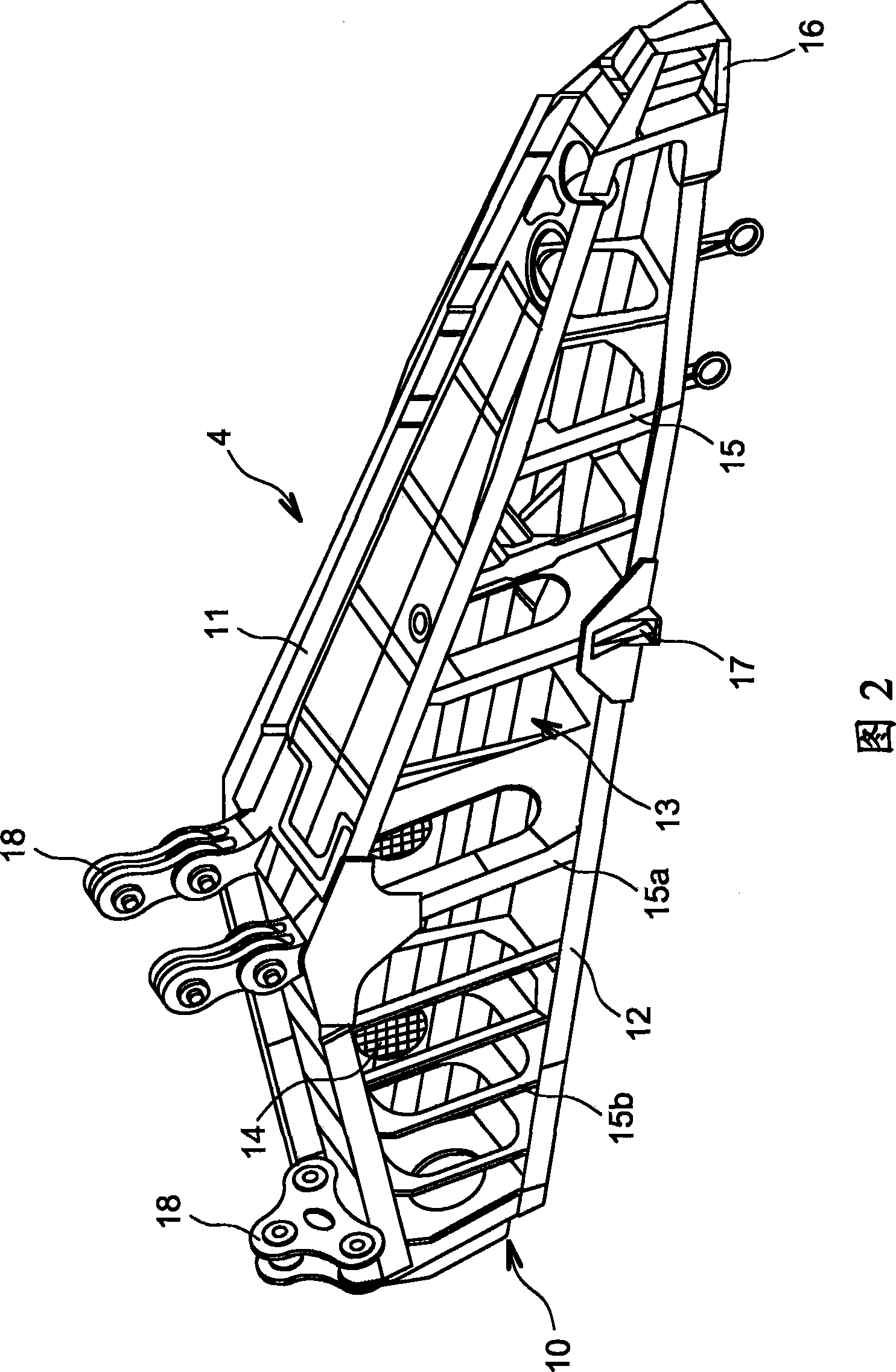
[0014] The main problem with this structure 10 is that it is difficult to assemble; obviously, the different ribs 15a, 15b have to be fixed to the spars 11, 12 one after the other, and their positions are precisely determined, in particular, in order for the engine to run optimized, their position is determined precisely by the fixed position of the suspension 16, 17 of the engine in particular
Furthermore, the different connection means increase the weight of the pylon 4, which has always been a disadvantage in aviation applications

Method used


Image

  • Monolithic framework engine mounting structure
  • Monolithic framework engine mounting structure
  • Monolithic framework engine mounting structure

Examples


Embodiment Construction

[0027] As mentioned above, the manufacture of the hanger is a long and complicated process. However, considering the loads imposed on the pylons and the safety conditions observed on the part of the aviation industry, few feasible solutions exist. For example, the essential function of the pylon in aircraft operation requires stringent reliability standards due to the inherent fail-safe function that a partial failure must be compensated for in any event.

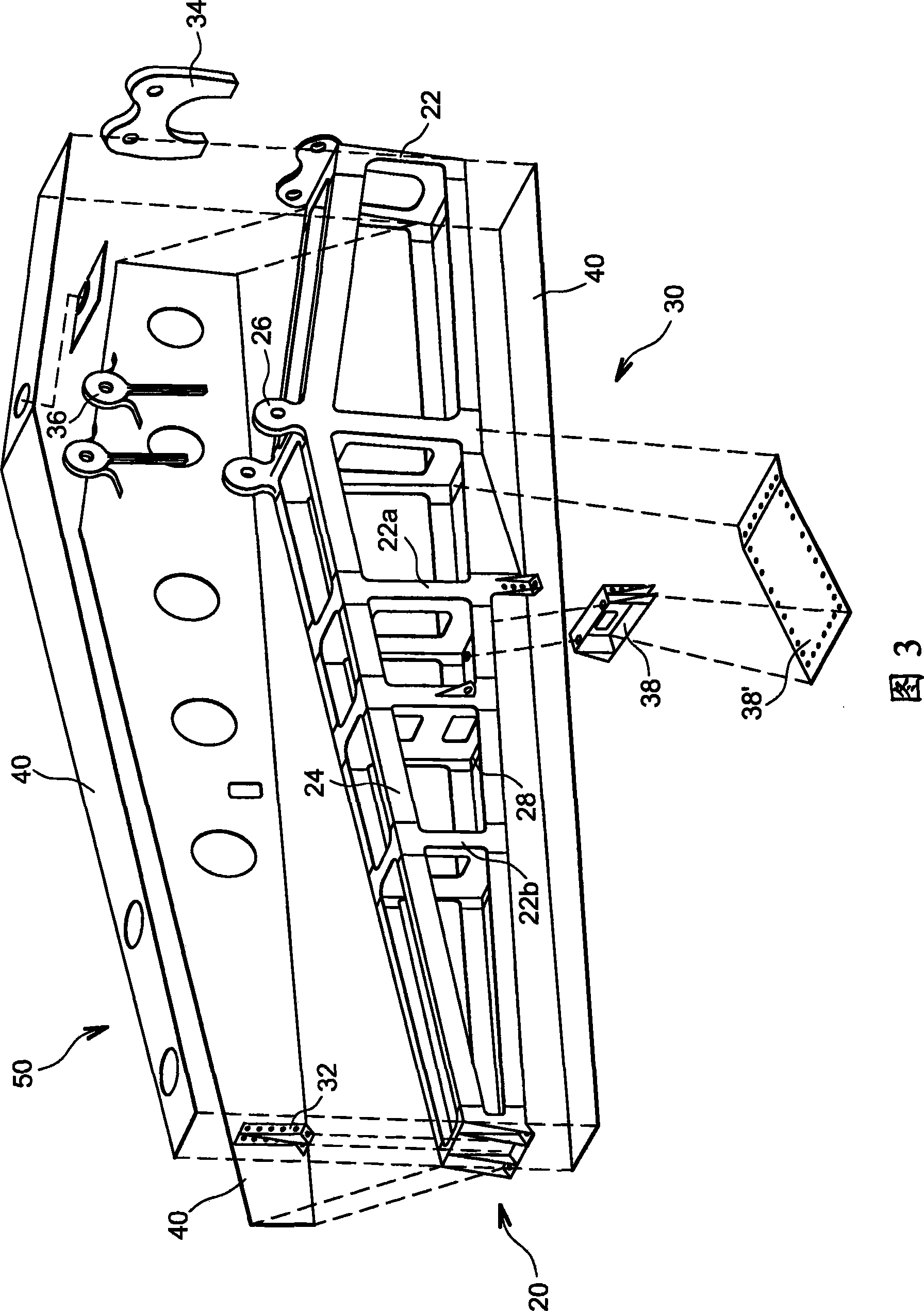
[0028] Therefore, the present invention proposes a type of hanger for which the frame (only the frame) is of the monolithic (or monolithic) and / or integrated type in order to reduce the structural Meet the requirements while reducing weight and simplifying the manufacturing process. In fact, the complete integration of the pylon structure is not sufficient to meet the required conditions; for example, if a crack occurs in the material of a monolithic pylon, this may propagate to other parts of the structure and create a ri...


PUM


Abstract

A structure for an aircraft engine assembly suspension pylori. The pylori includes a monolithic frame, manufactured for example by casting or welding, covered with mechanically assembled skins. Advantageously, stiffeners are mechanically fixed to points through which forces are applied. The dual structure makes it possible to take advantage of integration during manufacturing while respecting safety criteria due to mechanical assemblies.

Description

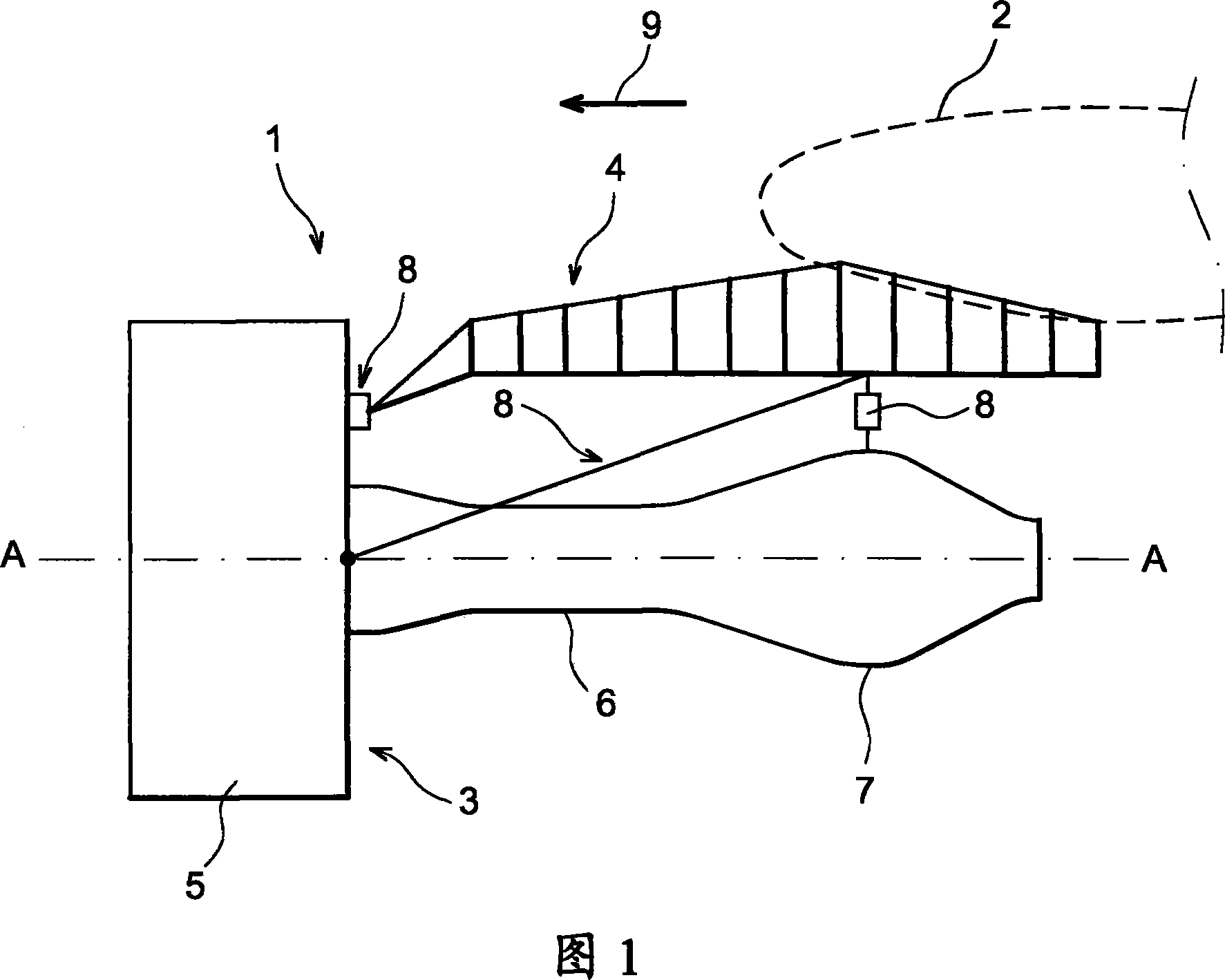
technical field [0001] Generally, the present invention relates to an aircraft engine pylon. This type of suspension is also known as EMS (Engine Mounting Structure, Engine Mounting Structure) and can be used, for example, to suspend a turbojet engine under the wing of an aircraft via above the wing. [0002] More specifically, the present invention relates to a novel hanger structure and its manufacturing method. Background technique [0003] In aircraft, pylons are designed to form a connection interface between an engine, such as a turbojet engine, and an aircraft wing. This mount transmits the forces generated by its associated turbojet engine to the structure of the aircraft and also enables the passage of fuel, electrical, hydraulic and air systems between the engine and the aircraft. [0004] Such as figure 1 As shown, an aircraft engine assembly 1 is designed to be fixed under a wing 2 of an aircraft and includes an engine such as a turbojet 3 and a suspension 4 ...

Claims


Application Information

Patent Timeline
Patent Type & Authority Patents(China)
IPC IPC(8): B64D27/26B64D27/40
CPCY02T50/44B64D27/26B64D2027/264Y10T29/49622Y02T50/40B64D27/402B64D27/40
Inventor 劳伦特·拉丰
Owner AIRBUS OPERATIONS (SAS)
Learn More