Container for cold storage

A technology for refrigerated containers and boxes, applied in the field of containers, can solve problems such as difficulty in painting construction, waste, and low welding efficiency, and achieve the effects of improving production efficiency and welding quality, reducing waste, and saving materials

Inactive Publication Date: 2008-10-01
CHINA INTERNATIONAL MARINE CONTAINERS (GROUP) CO LTD +1
View PDF0 Cites 6 Cited by
  • Summary
  • Abstract
  • Description
  • Claims
  • Application Information

AI Technical Summary

Problems solved by technology

[0003] (1) There are many pressing and assembling processes, and the efficiency is low;
[0004] (2) The welding with the bottom side beam is all used for manual welding, which has low welding efficiency and poor forming;
[0005] (3) The trough foam material does not have a heat insulation effect;
[0006] (4) The paint construction is difficult, resulting in a huge difference in the thickness of the paint film between the peak and the trough, and the waste is serious

Method used


Image

  • Container for cold storage
  • Container for cold storage
  • Container for cold storage

Examples


Embodiment Construction

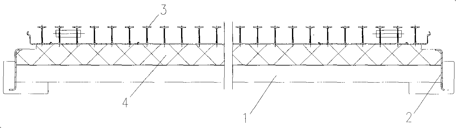
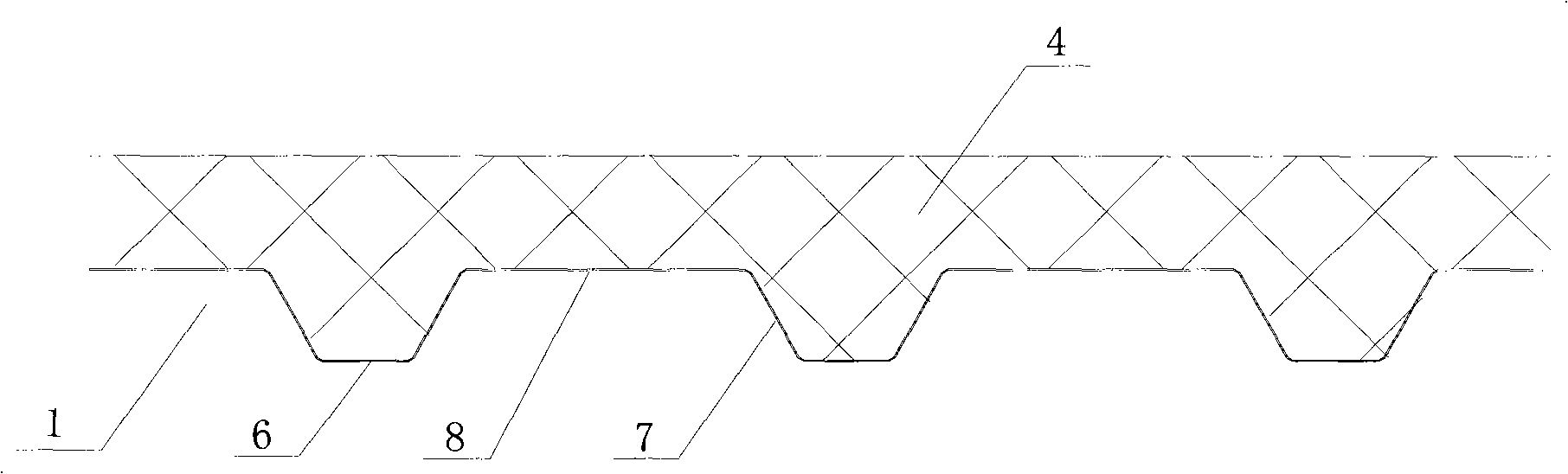
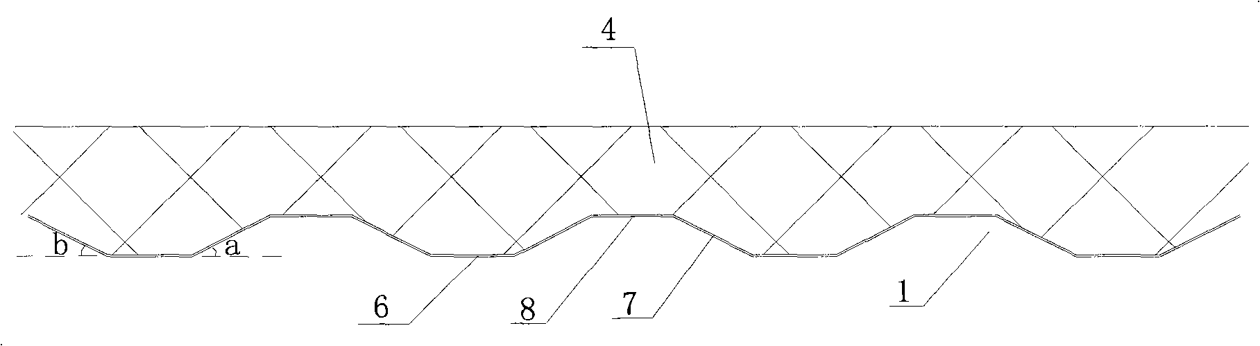
[0021] The present invention will be further described below in conjunction with the accompanying drawings and specific embodiments. in, figure 1 is a transverse sectional view of the floor of a refrigerated container; image 3 It is a partial longitudinal sectional view of the corrugated sub-floor and the foam material layer of the bottom plate of the refrigerated container of the present invention.

[0022] Such as figure 1 with image 3 As shown, the bottom plate of the refrigerated container of the present invention includes a floor 3 inside the box, a corrugated sub-floor 1 outside the box, a foam material layer 4 filled between the floor 1 and the corrugated sub-floor 3, and the corrugated sub-floor 1 is fixedly connected to the bottom side beam 2. The corrugated sub-floor 1 includes a plurality of crests 8 and troughs 6 of the same shape arranged alternately in sequence. The angles a or b formed by the directions are both less than 45°. The angle formed by the hypo...


PUM


Abstract

The invention relates to a refrigerated container. The soleplate of the refrigerated container comprises a floor arranged in the container body, an assistant corrugated floor arranged outside the container body, and a foaming material layer which is filled between the floor and the assistant floor; the assistant floor is connected with a bottom side beam and comprises a plurality of peaks and troughs with the same shape and arranged at intervals, and the part between the peak and the trough is an wave inclined edge. The refrigerated container is characterized in that the included angle between the wave inclined edge and the horizontal direction is less than 45 degrees. Compared with the prior art, the refrigerated container has the advantages of high welding quality, convenient painting, low cost, high production efficiency and good rigidness, etc.

Description

technical field [0001] This invention relates to a container and more particularly to an improved floor for refrigerated containers. Background technique [0002] The bottom plate of the existing refrigerated container is generally composed of the upper T floor and the lower sub-floor filled with foam material; among them, the corrugated sub-floor structure is widely used because of its good air leakage resistance and light weight. The sub-floor is generally formed by overlapping or splicing (welding or bonding) multiple corrugated sub-floors to form a whole sub-floor. Such as figure 1 with figure 2 As shown, the entire auxiliary floor 1 is welded on the bottom side beam 2 . Place the T floor 3 on one side of the auxiliary floor, and leave a certain distance between the two to fill the heat-insulating foam 4 . Since each corrugated sub-floor is welded or bonded to form the entire sub-floor, the sub-floor 1 and the bottom side beam 2 are welded together, so the air leaka...

Claims


Application Information

Patent Timeline
Patent Type & Authority Applications(China)
IPC IPC(8): B65D90/02B65D88/74
Inventor 宋卫国杨维廷
Owner CHINA INTERNATIONAL MARINE CONTAINERS (GROUP) CO LTD
Why Eureka
Try Eureka