
Automatic welding device for agricultural vehicle balance weight
An automatic welding and counterweight technology, which is applied in welding equipment, auxiliary welding equipment, welding/cutting auxiliary equipment, etc., can solve the problems of high welding quality requirements, poor welding quality of workpieces, and low welding efficiency, so as to improve welding quality and welding efficiency, low manufacturing cost, and compact size
- Summary
- Abstract
- Description
- Claims
- Application Information
AI Technical Summary
Problems solved by technology
Method used
Image

Examples
Embodiment Construction
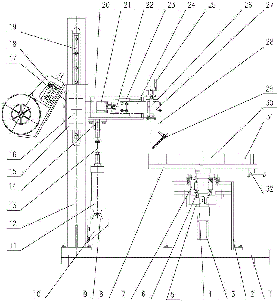
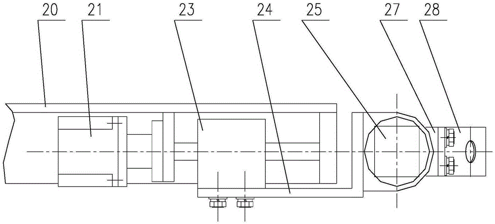
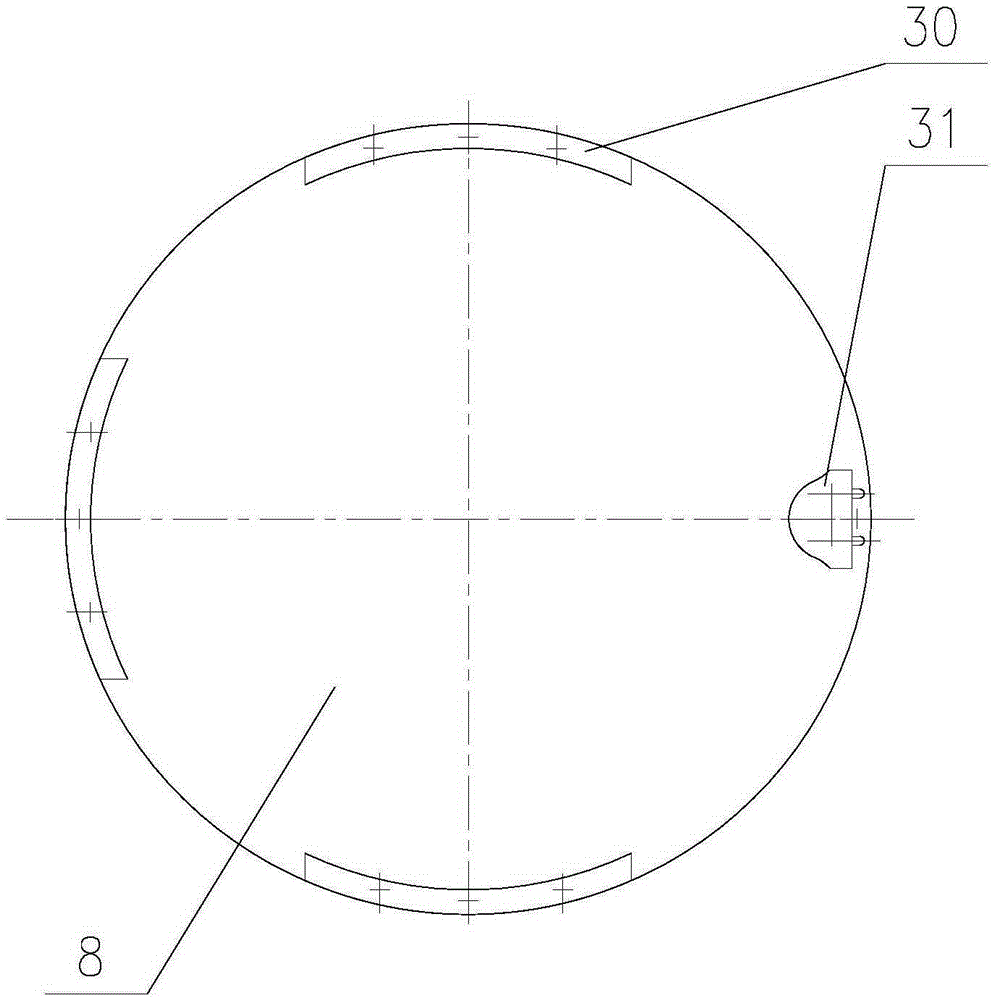
[0010] An automatic welding equipment for the counterweight body of agricultural vehicles, which is composed of a base, a workbench, a column, a lifting beam and a welding torch swing mechanism. 4. The structure of deceleration frame 5, rotating shaft 6, rotating shaft sleeve 7, worktable panel 8, arc positioning block 30, semicircular positioning block 31 and eccentric wheel clamping device 32, the column 12 has a lifting cylinder Frame 10, lifting cylinder hinge support 9, lifting cylinder 11, adjustable ejector rod 13 and linear guide rail 19 structure, described lifting beam has sleeve frame 15, slide block 16, wire feeder support 17, wire feeder 18 , lifting hinge support 14, cross arm frame 20, transverse motor 21, transverse lead screw 22 and transverse slider 23 structure, the workbench 2 is installed on the base 1 with bolts, and the rotating motor 3 is connected with the reducer 4 and installed with bolts On the reducer frame 5, the reducer frame 5 is installed under...
PUM
 Abstract
Description
Claims
Application Information