Optical device comprising a structure for avoiding reflections

A technology of optical devices and mirrors, which is applied in the direction of optical components, optics, instruments, etc., can solve the problems of multiple reflections and interference without display

Active Publication Date: 2008-10-08
FRAUNHOFER GESELLSCHAFT ZUR FOERDERUNG DER ANGEWANDTEN FORSCHUNG EV
View PDF0 Cites 18 Cited by
  • Summary
  • Abstract
  • Description
  • Claims
  • Application Information

AI Technical Summary

Problems solved by technology

The intensity of the latter is rather low compared to the main beam paths 5a and 5c respectively, but as has been estimated previously from the emission disp

Method used


Image

  • Optical device comprising a structure for avoiding reflections
  • Optical device comprising a structure for avoiding reflections
  • Optical device comprising a structure for avoiding reflections

Examples


Embodiment Construction

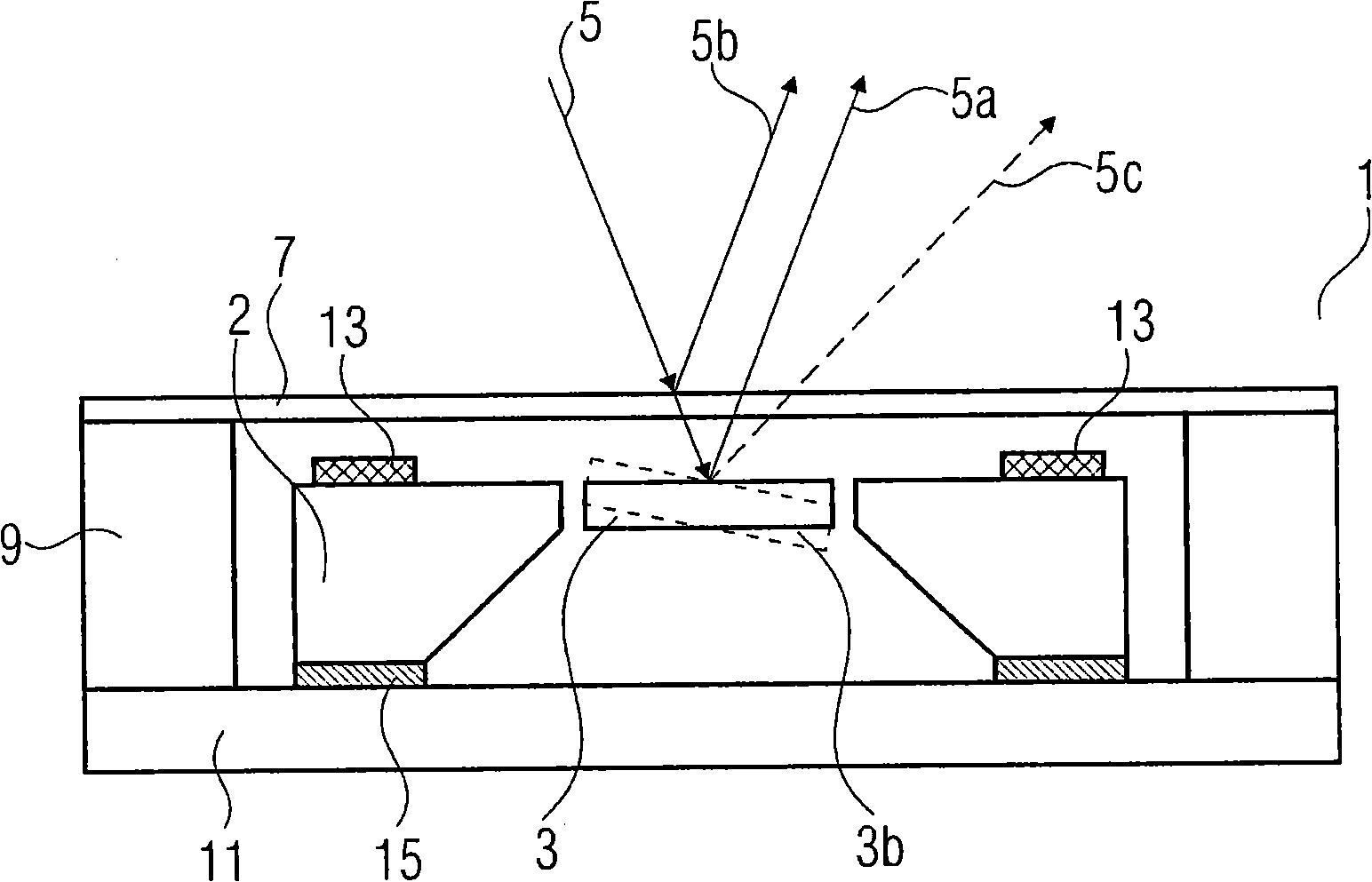
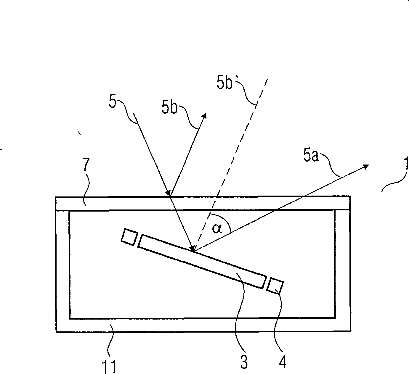
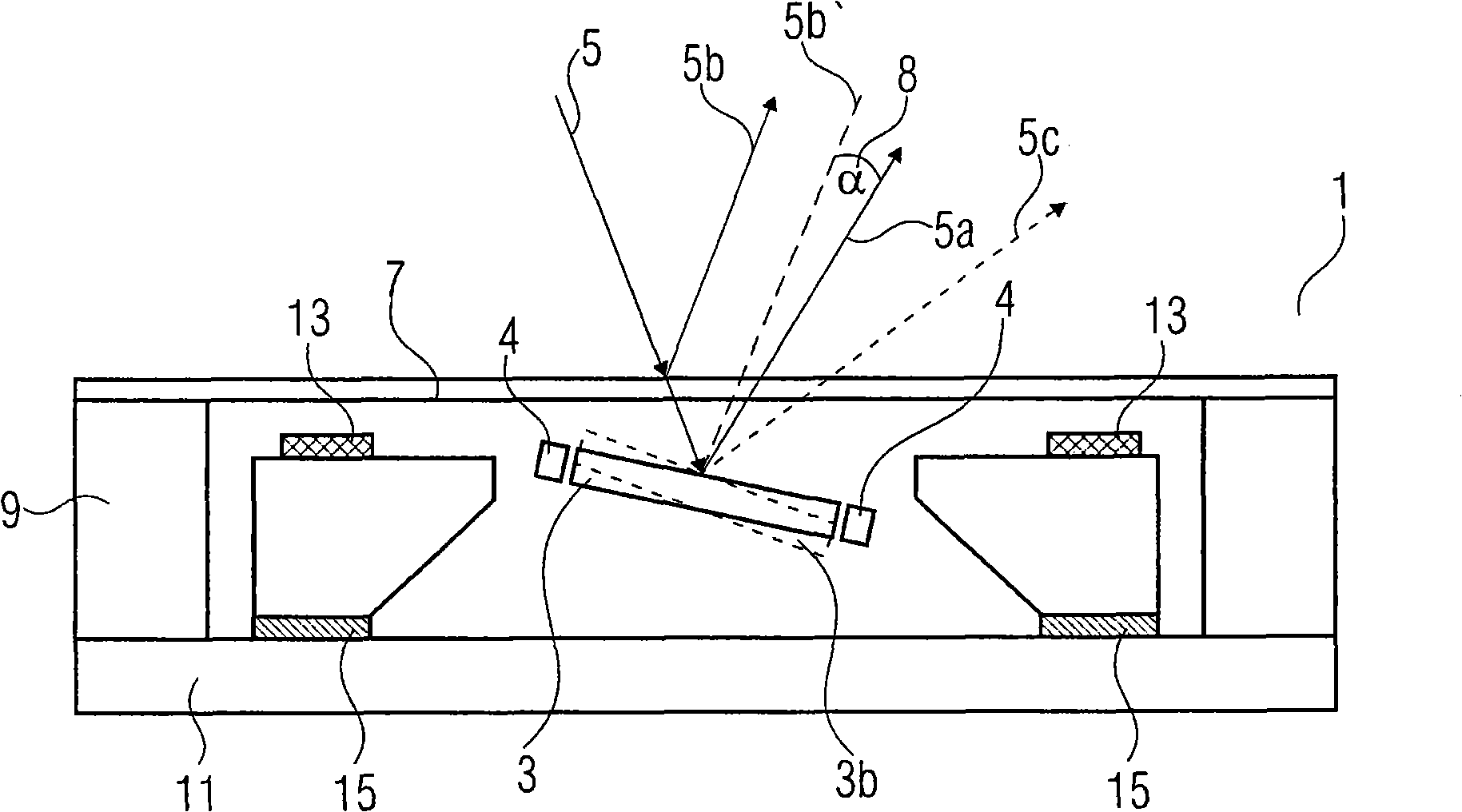
[0027] figure 2 is a schematic diagram of an optical device 1 according to an embodiment of the invention. The optical device 1 comprises a tiltable optically functional structure 3 interacting with electromagnetic radiation incident thereon. The optical functional structure 3 consists of several components, such as the additional frame structure 4 . In addition, the optical device 1 comprises a protective structure 7 associated with the optically functional structure 3 and transparent to electromagnetic radiation 5 . The optically functional structure 3 is arranged in an oblique manner relative to the protective structure 7, so that, in the non-deflected position, the main beam path 5 of the electromagnetic radiation interacting with the optically functional structure 3 through the protective structure 7 is relative to the electromagnetic radiation reflected by the protective structure 7 The secondary beam path 5b has an angle α. exist figure 2 In , the angle α is shown...


PUM


Abstract

An optical device includes a deflectable optical functional structure for interacting with electromagnetic radiation incident thereon, and a protective structure which is associated to the optical functional structure and at least partly transparent for the electromagnetic radiation. The optical functional structure is arranged in a manner tilted relative to the protective structure so that, in a non-deflected position of the optical functional structure, a main beam path of the electromagnetic radiation which interacts with the optical functional structure through the protective structure has an angle relative to a sub-beam path of the electromagnetic radiation reflected at the protective structure.

Description

technical field [0001] The invention relates to an optical device in which disturbing reflections of electromagnetic radiation are prevented within the operating range of the optical device. In particular, the present invention relates to micromachined 1D and 2D scanner mirrors, phase shifting mirrors and other optical components whose function is affected by the interaction of electromagnetic radiation reflecting off glass covers and / or protective structures with the optics . Background technique [0002] In such components, the glass cover and / or the protective structure have the function of protecting the device from dust and impurities and / or ensuring a certain ambient atmosphere, such as a certain pressure, a certain humidity or a certain type of gas. At the same time, light beams and / or electromagnetic radiation can be coupled in and output. The cover glass can be deposited on the wafer level during the manufacturing process, so-called wafer-level packaging, or, for...

Claims


Application Information

Patent Timeline
IPC IPC(8): G02B26/08
CPCG02B26/0833G02B27/0018
Inventor 哈拉尔德·琛克提诺·詹德纳
Owner FRAUNHOFER GESELLSCHAFT ZUR FOERDERUNG DER ANGEWANDTEN FORSCHUNG EV
Why Eureka
Try Eureka