Output type multi-bearing-point independent suspension

A technology of independent suspension and frame, applied in the direction of suspension, elastic suspension, cantilever installed on the pivot, etc., can solve the problems of no change innovation, limited space of bearing points, frequent load changes, etc., to achieve space Take advantage of the effects of optimization, reduced vehicle height, increased number

Inactive Publication Date: 2015-05-06
石宇 +1
View PDF5 Cites 13 Cited by
  • Summary
  • Abstract
  • Description
  • Claims
  • Application Information

AI Technical Summary

Problems solved by technology

The double wishbone suspension has been used for many years, because of many structural parts, changing environment, frequent load changes, continuous work, limited space for bearing points, etc., there has been no change and innovation

Method used


Image

  • Output type multi-bearing-point independent suspension
  • Output type multi-bearing-point independent suspension
  • Output type multi-bearing-point independent suspension

Examples


Embodiment approach 1

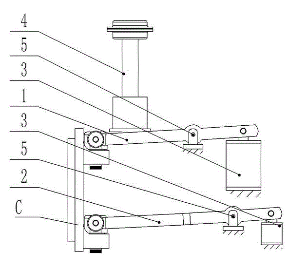
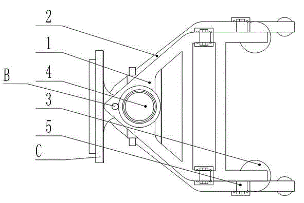
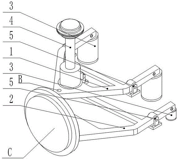
[0046] The cover implementation is the folding back method of the wishbone positioning shaft, please refer to figure 1 , figure 2 with image 3 As shown,

[0047] This embodiment is composed of an upper fork arm 1, a lower fork arm 2, an elastic element 3, a shock absorber 4, and a fork arm positioning shaft 5; the upper fork arm 1 and the lower fork arm 2 are A-shaped structural parts, The front ends of the upper fork arm 1 and the lower fork arm 2 are respectively connected to the upper and lower suspension points of the wheel C through the king pin B, and the middle ends of the upper fork arm 1 and the lower fork arm 2 are respectively connected to the vehicle through the fork arm positioning shaft 5 On the frame, an elastic element 3 is arranged between the bottom of the rear end of the upper fork arm 1 and the frame, and a shock absorber 4 is installed on the upper part of the front end of the upper fork arm 1;

[0048] An elastic element 3 may also be provided between the bo...

Embodiment approach 2

[0052] This implementation is the way of wishbone positioning shaft torsion bar, please refer to Figure 5 , Image 6 , Figure 7 with Figure 8 As shown,

[0053] This embodiment is composed of an upper wishbone 1, a lower wishbone 2, a wishbone positioning shaft 5, a torsion bar 6, a shock absorber 4, and a torsion bar seat 7. The upper wishbone 1 and the lower wishbone 2 are A-shaped structural part, the front ends of the upper and lower wishbone 1 and 2 are respectively connected to the upper and lower hanging points of the wheel C through the kingpin B, and the rear ends of the upper and lower wishbone 1 and 2 are connected through a torsion bar 6 and the torsion bar base 7 are connected to the frame, and a shock absorber 4 is installed between the upper front end of the upper fork arm 1 and the frame.

[0054] The wheel C bounces up and down to drive the front end of the upper fork arm 1 to move upwards, and rotate along the fixed point behind, so that the two torsion bars 6 ...

Embodiment approach 3

[0056] This implementation is a leverage derivation method, please refer to Picture 9 , Picture 10 with Picture 11 As shown,

[0057] This embodiment is composed of an upper fork arm 1, a lower fork arm 2, a fork arm positioning shaft 5, a connecting rod 8, a lead-out lever shaft 9, a lead-out lever 10, an elastic element 3, and a shock absorber 4. Arm 1 and lower wishbone 2 are A-shaped structural parts. The front ends of upper wishbone 1 and lower wishbone 2 are respectively connected to the upper and lower hanging points of wheel C through kingpin B, upper wishbone 1 and lower fork The rear end of the arm 2 is respectively connected to the frame through the fork arm positioning shaft 5, the front bottom surface of the upper fork arm 1 extends two fork arm hanging shafts 81, and the lower end of each fork arm hanging shaft 81 is connected to the leading lever 10 through the connecting rod 8 to lead out The middle end of the lever 10 is articulated with the frame through the ...


PUM


Abstract

The invention discloses an output type multi-bearing-point independent suspension, which comprises an upper fork arm, a lower fork arm, elastic elements, a shock absorber and fork arm-positioning pivots; the upper fork arm and the lower fork arm are A-shaped structural parts, the front ends of the upper fork arm and the lower fork arm are respectively connected with the upper suspension point and lower suspension point of a wheel through main pins, the shock absorber is mounted on the top of the front end of the upper fork arm, and the rear ends of the upper fork arm and the lower fork arm are connected with a chassis through the elastic elements. A corresponding available space is expanded around the upper fork arm and the lower fork arm, reasonable bearing pivot points and transfer parts of the chassis are structured, the lever principle, the torsion bar principle and the principle of moments are utilized, so that double-fork arm pivotal suspension point motion can absorb bearing elastic force by means of returning force and the arms of force or direction change, the conventional one-point supporting elastic element is changed into the multiple multi-point supporting elastic elements, consequently, the force applied on the wheel is decomposed by multiple points, and thereby average running speed is increased. The increase in the number of the elastic elements and the reasonable arrangement of the elastic elements can reduce the height of a vehicle, optimize space utilization and improve the stability and running smoothness of the vehicle.

Description

technical field [0001] The invention relates to an applied part of an automobile chassis, belongs to the technical field of passenger cars and commercial vehicles, and is an innovative automobile suspension system. Background technique [0002] Suspension system is the general term for all transmission connection devices between the frame (axle) and the wheels of the car. The impact force of the car body and attenuate the vibration caused by it, so as to ensure that the car can run smoothly. [0003] Early automobiles mainly used leaf springs as the non-independent suspension of elastic elements. With the development, the elastic elements also developed from leaf springs to coil springs, torsion bar springs, air springs, rubber springs and oil-gas springs. Existing high-end vehicles mostly use independent suspensions, such as wishbone, trailing arm, single cantilever, candle, McPherson, multi-link and active suspension. [0004] Double wishbone independent suspension is a ...

Claims


Application Information

Patent Timeline
Patent Type & Authority Applications(China)
IPC IPC(8): B60G3/18B60G15/00
CPCB60G3/20B60G11/50B60G15/00B60G11/181B60G11/20B60G2200/144B60G2204/421B60G2204/422B60G3/18B60G7/008B60G13/003B60G2200/1322B60G2204/143B60G2204/416
Inventor 石宇邢艳琦刘辉田家涛刘太峰颜炳文韩同超石国祥
Owner 石宇
Why Eureka
Try Eureka