Device for examining workpieces

A workpiece and inspection point technology, which is applied in the field of inspecting workpieces, especially circuit board devices, can solve problems such as the inability to obtain tool position information, and achieve high-precision results

Inactive Publication Date: 2008-10-08
MIDAS PRIVATE EQUITY
View PDF1 Cites 2 Cited by
  • Summary
  • Abstract
  • Description
  • Claims
  • Application Information

AI Technical Summary

Problems solved by technology

but can't get information about the location of the tool

Method used


Image

  • Device for examining workpieces
  • Device for examining workpieces
  • Device for examining workpieces

Examples


Embodiment Construction

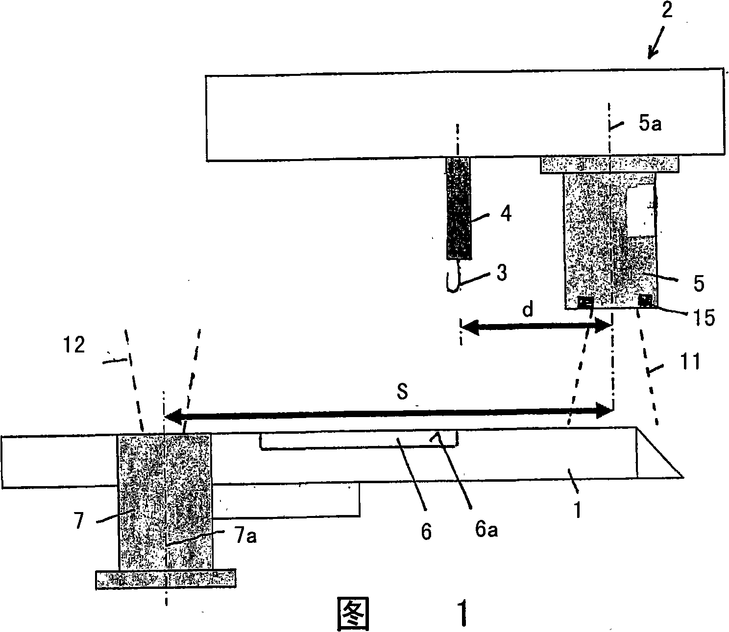
[0027] The device from FIG. 1 comprises a seat 1 for a workpiece 6 on which the measurement is carried out and which is arranged in a workpiece plane 6 a. A tool 3 in the form of a hook is suspended in the measuring head 2 via a tension detection device 4 . Furthermore, the detection range of the camera 5 , which is fixed to the measuring head 2 , is indicated with reference numeral 11 . The mechanical offset d is defined as the distance of the axis 5 a of the camera 5 from the tool 3 . In the socket 5 is fixed a further camera 7 with an upwardly pointing detection cone 12 into which the tool 3 and reference points 15 can be introduced, which are attached to the camera 5 and thus to the to measuring head 2.

[0028] The calibration process can now be carried out in such a way that the movement of the measuring head 2 first causes the tool 3 to be oriented towards the optical axis 7 a of the other camera 7 before the axis 5 a of the camera 5 is aligned with the axis 7 a by me...


PUM


Abstract

The invention relates to a device for examining workpieces (6), in particular, circuit cards, comprising an examination tool, which is clamped to the measuring head (2), which can be displaced in relation to the workpiece (6) on a workpiece plane, and also comprising an optical observation device which is used to control the measuring head (2). The optical observation device is embodied as a camera (5), which is mounted on the measuring head (2) and which comprises an optical axis (5a), such that a simple, rapid and reliable measurement can be carried out. Said axis is essentially perpendicular to the workpiece plane (6a), and a calibration device is provided in order to determine the mechanical offset (d) which is the distance of the tool (3) from the optical axis (5a) of the camera (5). The invention also relates to a method which can be carried out using the above-mentioned device.

Description

technical field [0001] The invention relates to a device for inspecting workpieces, especially circuit boards, comprising an inspection tool clamped in a measuring head movable relative to the workpiece in the plane of the workpiece, the device also comprising optics for controlling the measuring head Observation device. Background technique [0002] In the manufacture of circuit boards or other electronic components, it is often necessary to test the quality of solder joints. This involves, for example, testing the contact of the microprocessor with the corresponding point on the board by introducing a tool configured as a small hook under the connecting wire and then tearing the connecting wire with the help of the hook. The force required to tear apart the connecting wire is measured, which is a measure of the quality of the welded joint. Since the workpieces and tools to be inspected are by definition very small, the movements must be controlled with high precision, wh...

Claims


Application Information

Patent Timeline
Patent Type & Authority Applications(China)
IPC IPC(8): H05K13/08G01N3/00
CPCH05K13/08G01N3/00G01N2203/021G01N2203/0296H05K13/089H05K13/0815
Inventor M·施米德鲍尔M·克瑞特施姆G·斯托丁格
Owner MIDAS PRIVATE EQUITY
Why Eureka
Try Eureka