Assembling method of sealing ring of shaft rod in finisher on numerical control lathe

A technology of numerical control machine tools and assembly methods, applied in metal processing, metal processing equipment, manufacturing tools, etc., can solve problems affecting product quality, missing seal rings on shafts, small shaft diameters, etc., and improve the success rate of suction , Improve assembly work and improve installation efficiency

Active Publication Date: 2018-06-26
南通市方大机械厂
View PDF4 Cites 4 Cited by
  • Summary
  • Abstract
  • Description
  • Claims
  • Application Information

AI Technical Summary

Problems solved by technology

The original shaft assembly work is performed by a single person in batches. When installing the sealing ring in the shaft, because the work is a simple repetitive action, the operator repeats the operation for a long time, which is prone to mental fatigue and paralysis in the mind, resulting in the inside of the shaft. The sealing ring is missing, and because the sealing ring is installed in the ring groove of the shaft, the worker cannot directly observe whether there is a missing sealing ring with the naked eye, and when the worker confirms by hand, because some shafts have small diameters It cannot be implemented, which makes it difficult for workers to find out the shaft with the missing sealing ring, which affects product quality. In actual producers, product rework often occurs due to missing sealing rings

Method used


Image

  • Assembling method of sealing ring of shaft rod in finisher on numerical control lathe
  • Assembling method of sealing ring of shaft rod in finisher on numerical control lathe
  • Assembling method of sealing ring of shaft rod in finisher on numerical control lathe

Examples


Embodiment Construction

[0034] The specific embodiments of the present invention will be further described in detail below in conjunction with the accompanying drawings and embodiments of the specification: The present invention relates to a method for assembling the sealing ring of the inner shaft of the trimmer on a CNC machine tool, which is specifically realized by using a sealing ring assembly machine.

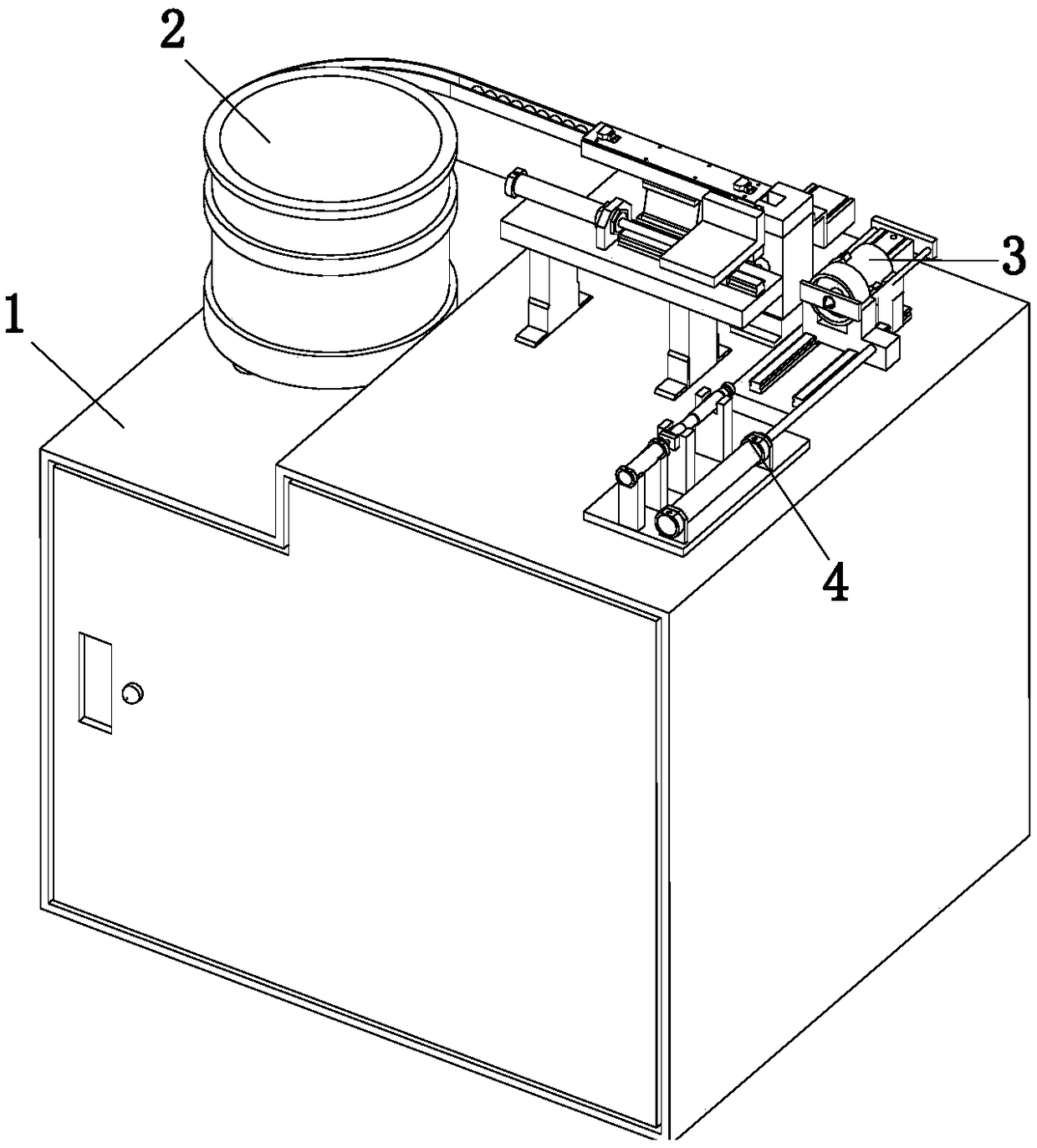
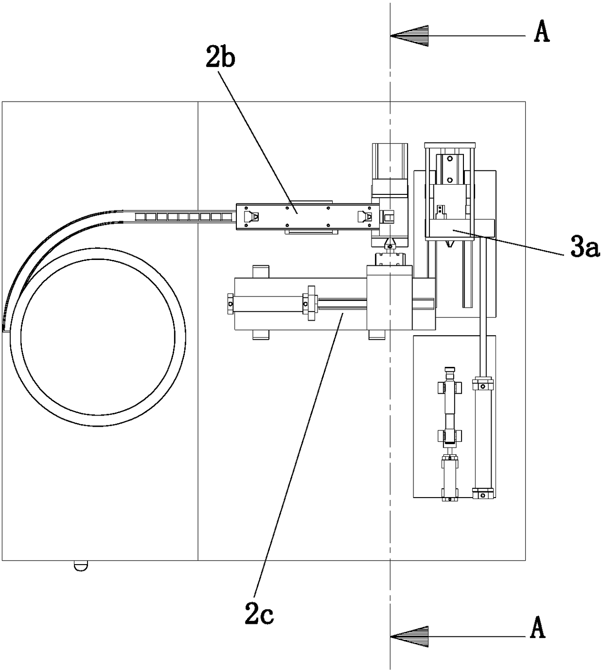
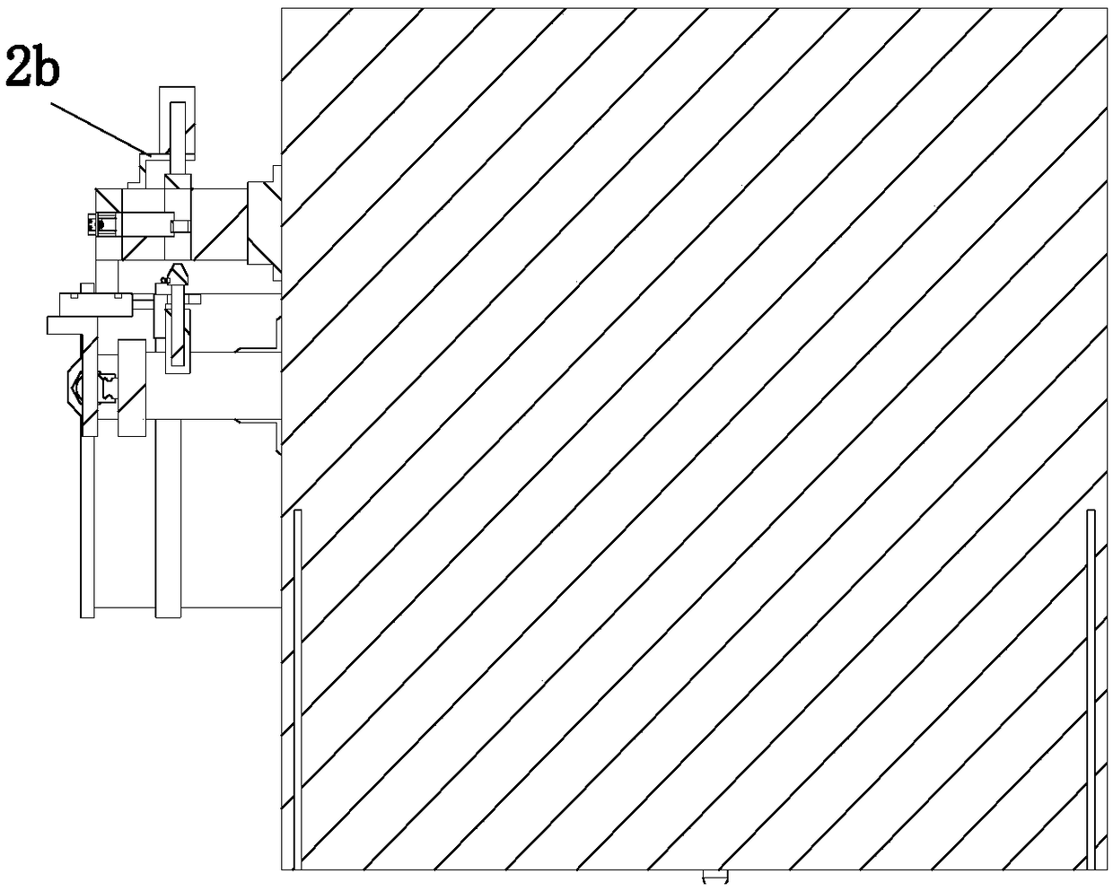
[0035] refer to Figure 1 to Figure 12 The sealing ring assembly machine shown includes a working cabinet 1, a sealing ring feeding device 2 installed on the top of the working cabinet 1 for intermittent feeding of several sealing rings to be clamped, and a sealing ring feeding device 2 installed at the output end of the sealing ring feeding device 2 A sealing ring positioning device 3 for positioning a single sealing ring to be assembled and a shaft positioning device 4 installed on the top of the working cabinet 1 and located at the output end of the sealing ring positioning device 3 for limiti...


PUM


Abstract

The invention relates to the technical field of sealing ring assembling equipment, and particularly relates to an assembling method of a sealing ring of a shaft rod in a finisher on a numerical control lathe. The method is performed on the basis of an assembling machine for the sealing ring of the shaft rod in the finisher on the numerical control lathe, wherein the assembling machine comprises aworking cabinet, a sealing ring feeding device, a sealing ring positioning device and a shaft rod positioning device; the sealing ring feeding device comprises a vibrating feeding plate, a sealing ring feeding part and a sealing ring transferring part; the sealing ring positioning device comprises a sealing ring clamping part, a sealing ring propping part and a transferring conveying part; the shaft rod positioning device comprises a shaft rod positioning part which is mounted on the top part of the working cabinet, and a shaft rod limiting part which is used in match with the shaft rod positioning part; the shaft rod limiting part is capable of fixing the shaft rod to be assembled to the shaft rod positioning rod. According to the method, a series of automatic assembling works can be performed, so that the labor output is decreased; the problem that workers directly observe with naked eyes, resulting in neglected assembling of the sealing ring, can be avoided; the product quality is improved; and the circumstance of rework caused by frequent neglected assembling of the sealing ring in actual production can be reduced.

Description

technical field [0001] The invention relates to the technical field of sealing ring assembly equipment, in particular to a method for assembling the sealing ring of the inner shaft of a trimmer on a numerically controlled machine tool. Background technique [0002] At present, the piston cylinder of the commonly used hydraulic or pneumatic disc dresser is slidably equipped with a piston shaft, and a plurality of ring grooves are arranged on the outer peripheral wall of the piston shaft. A sealing ring that is tightly matched between the shaft rod and the dresser, and the main function of the sealing ring is to prevent leakage and dust. The original shaft assembly work is performed by a single person in batches. When installing the sealing ring in the shaft, because the work is a simple repetitive action, the operator repeats the operation for a long time, which is prone to mental fatigue and paralysis in the mind, resulting in the inside of the shaft. The sealing ring is mi...

Claims


Application Information

Patent Timeline
Patent Type & Authority Applications(China)
IPC IPC(8): B23P19/00
Inventor 段建英王峰马克斯顿
Owner 南通市方大机械厂
Why Eureka
Try Eureka