Rolling die cutter roller with improved structure

A technology of improving the structure and rolling die, applied in the field of machinery, can solve the problems of short service life, cracks, and sticking of the cutting edge of the die-cutting knife roll, and achieve the effect of prolonging the service life

Inactive Publication Date: 2008-10-15
谢兆琪
View PDF0 Cites 10 Cited by
  • Summary
  • Abstract
  • Description
  • Claims
  • Application Information

AI Technical Summary

Problems solved by technology

This factor leads to chipping and cracks on the edge line of the upper knife roller during actual production and use, so that the cutting edge of the product often sticks and cuts continuously during the cutting process, and the service life of the die-cutting knife roller is very short. , low production efficiency, and can not be matched with high-speed brand production equipment and other defects

Method used


Image

  • Rolling die cutter roller with improved structure
  • Rolling die cutter roller with improved structure
  • Rolling die cutter roller with improved structure

Examples


Embodiment Construction

[0020] The following are specific embodiments of the present invention and in conjunction with the accompanying drawings, further describe the technical solution of the present invention, but the present invention is not limited to these embodiments.

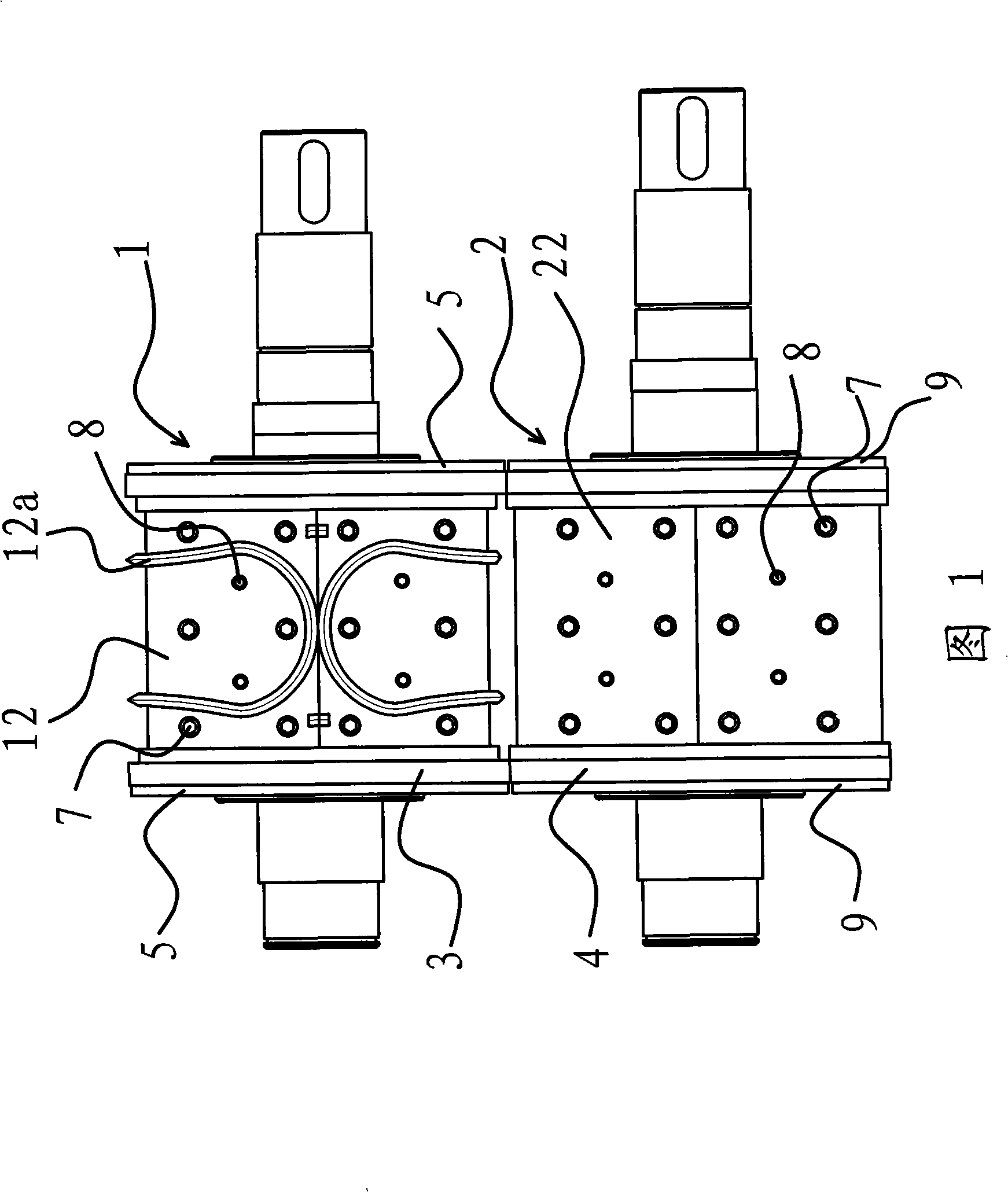
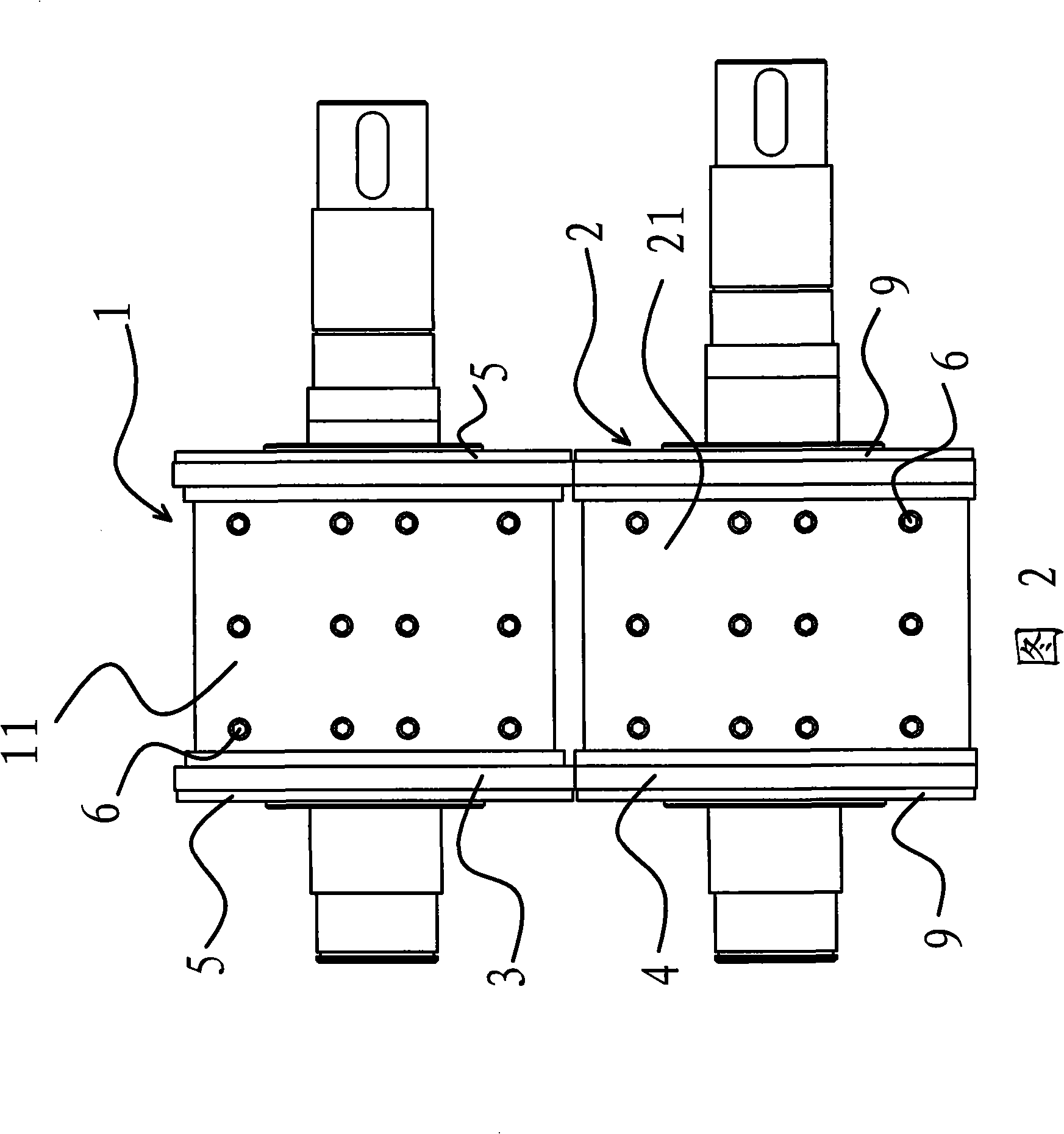
[0021] As shown in Fig. 1 and Fig. 2, the rolling die cutter roller of the improved structure includes an upper roller 1, a lower roller 2 and a power mechanism that can drive the upper roller 1 and the lower roller 2 to rotate, and the upper roller 1 And the lower roller 2 is installed on the frame, and the power mechanism is a servo motor.

[0022] A groove 11 is provided on the surface of the upper roller 1 in the circumferential direction, and two semicircular knife blocks 12 are embedded in the groove 11, and the knife blocks 12 have blade edges 12a. A fastening screw hole 6 is provided in the first groove 11 , and a screw hole 7 and an extraction hole 8 cooperating with the upper roller 1 are provided on the surface of the...


PUM


Abstract

The invention provides a rolling mould-cutting knife roller with improved structure and belongs to the technology field of machinery. The invention solves the problems that the prior rolling mould-cutting knife roller has short service life and low production efficiency. The rolling mould-cutting knife roller with the improved structure comprises an upper drum, a lower drum and a power mechanism capable of driving the upper and the lower drums to rotate. The upper and the lower drums are mounted on a machine frame, cylindrical shaped upper roller bearers are respectively arranged on two ends of the upper drum, and cylindrical shaped lower roller bearers in contact with the upper roller bearers are respectively arranged on two ends of the lower drum. The upper roller bearers are sleeved on the upper drum and the lower roller bearers are sleeved on the lower drum. An adjusting mechanism capable of adjusting the space between the upper and the lower drums by moving either of the roller bearer shafts and axially positioning the roller bearers on the drums after the roll bearers are adjusted is arranged between the adjacent upper and the lower roller bearers. The rolling mould-cutting knife roller with the improved structure is characterized by simple structure, high efficiency and long service life.

Description

technical field [0001] The invention belongs to the technical field of machinery, and in particular relates to a rolling die-cutting knife roller for die-cutting household paper products. Background technique [0002] At present, in the production industry of disposable sanitary products, the integral rotary die rolling die cutter roller has been widely used to cut various types of women's sanitary napkins, sanitary pads, adults, baby diapers, pet pads, A series of products such as medical mattresses and toilet seats. [0003] Existing rotary die-cutter rollers, engrave convex die-cutting blades of various disposable hygiene product patterns on the surface of the upper roller, the lower roller is a smooth roller, and the upper and lower rollers are installed on the mold of the sanitary product production equipment. On the cutting station (frame), the product raw materials conveyed by the automatic line equipment pass between the upper and lower rollers of the die-cutting st...

Claims


Application Information

Patent Timeline
Patent Type & Authority Applications(China)
IPC IPC(8): B26D1/12B26D7/26
Inventor 谢兆琪
Owner 谢兆琪
Why Eureka
Try Eureka