Sliding mechanism

A sliding mechanism and component technology, used in mechanical equipment, linear motion bearings, bearings, etc., can solve the problems of high maintenance costs, troublesome and troublesome for users, increase market acceptance, save parts costs, and reduce maintenance costs Effect

Inactive Publication Date: 2008-10-15
丁三郎 +1
View PDF0 Cites 2 Cited by
  • Summary
  • Abstract
  • Description
  • Claims
  • Application Information

AI Technical Summary

Problems solved by technology

[0003] However, the sliding parts installed in the track are generally the most commonly used bearings and linear screws, because the linear screw must match the length of the track installation path, intercept the same length and set it along the track, so it is more troublesome; The way the bearing slides along the track groove is relatively simple and eas

Method used


Image

  • Sliding mechanism
  • Sliding mechanism
  • Sliding mechanism

Examples


Embodiment Construction

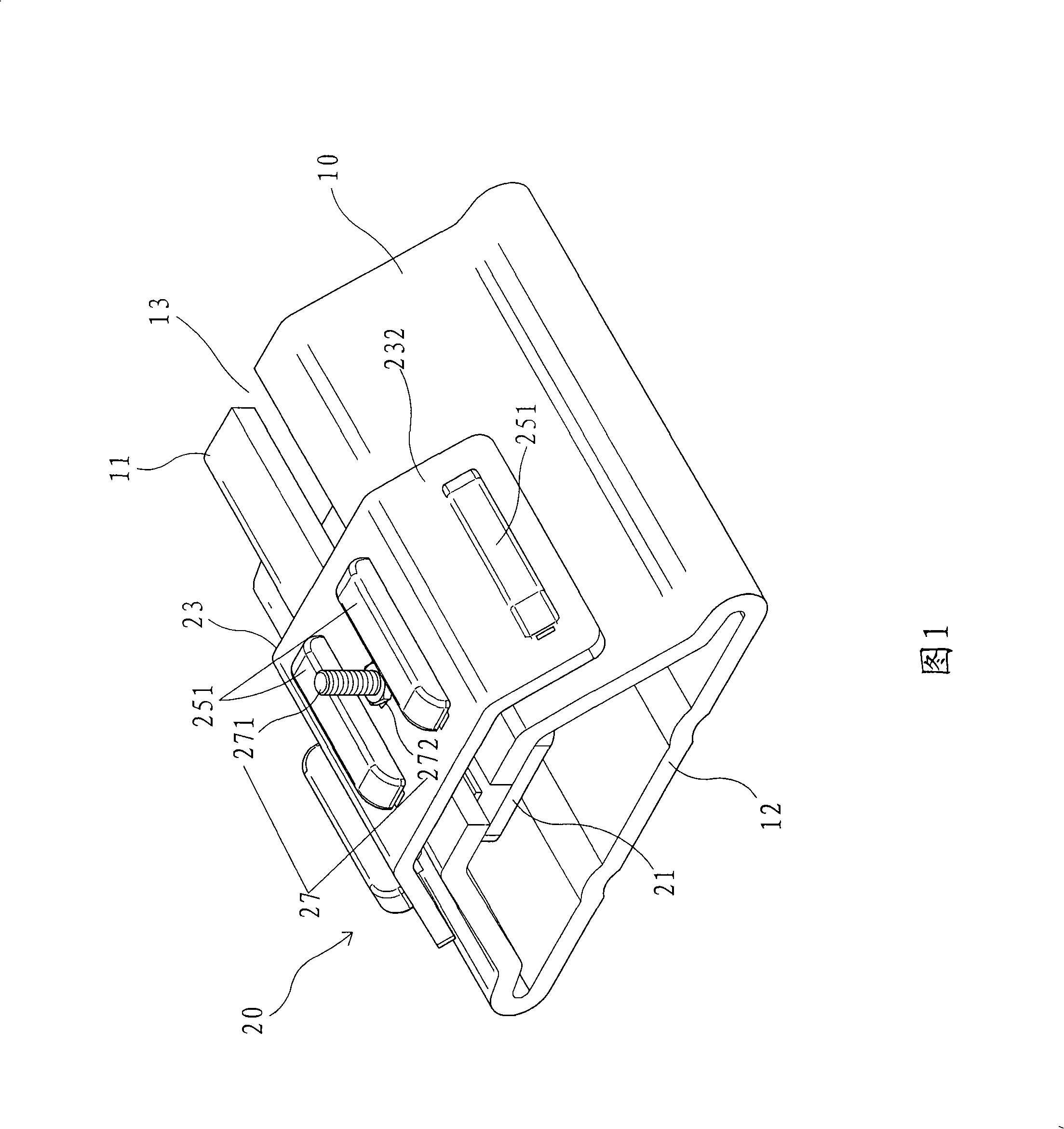
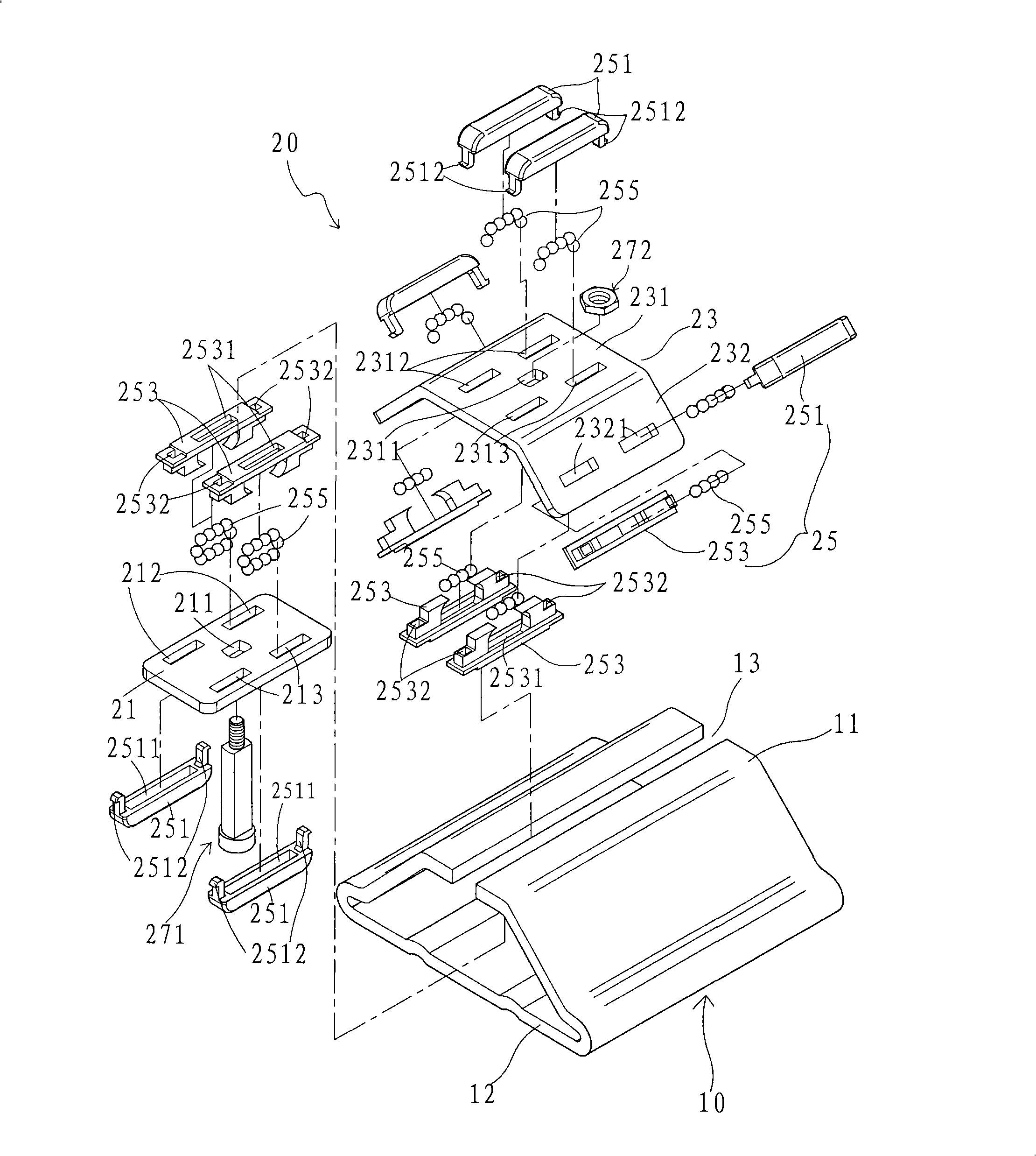
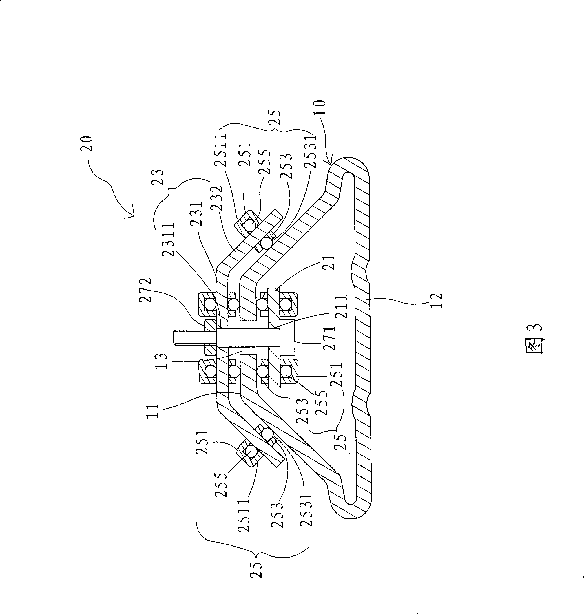
[0042] Please refer to Figures 1 to 3, a sliding mechanism 20 provided by the present invention is installed on a rail 10 in the shape of a hollow plate column, and can slide along a groove 13 provided at the center of the upper end of the rail 10 Displacement person, in the track 10 in the first preferred embodiment of the present invention, it is generally common that its upper bottom 11 width is less than its lower bottom 12 widths and generally is " trapezoidal " shape, and a kind of present invention The sliding mechanism 20 mainly includes: a first plate 21, a second plate 23, a plurality of roller members 25 including a main member 251, a secondary member 253, a plurality of ball bodies 255, and a positioning assembly 27; of which

[0043] The first plate 21 is a long rectangular plate with a width slightly larger than the width of the groove 13 of the track 10, and is arranged on the inside of the track 10 directly below the groove 13, at the center of the plate. Ther...


PUM


Abstract

The invention discloses a sliding mechanism which is arranged on a hollow plate-columnar track and can slide and shift along a groove on the track. The sliding mechanism comprises a first plate element, a second plate element and a plurality of rolling body members, wherein, the first plate element has a width which is more than the width of the groove and is arranged at the lower part of the groove, paired two groups of through holes are arranged on the first plate element; the second plate element is arranged crossly the outside of the track based on the frame of the track, paired two groups of through holes are arranged on the second plate element; the plurality of rolling body members are clamped above and under the through holes of the first plate element and the second plate element by a primary member and an auxiliary member, a plurality of rolling ball bodies are received in the members so that outer circumference faces of the rolling ball bodies are contacted and supported with a top surface and a bottom surface of two lateral sides of the groove. The sliding mechanism provides a simple motion mechanism which can make reciprocating slippage stably.

Description

technical field [0001] The present invention relates to a sliding mechanism, in particular to a motion mechanism that can be designed in the form of a track with a non-linear screw and a non-bearing device, and its components can simply reciprocate and slide, and can slide smoothly on the track shift. Background technique [0002] The conventionally known sliders installed in the generally hollow plate-shaped rails aim to reciprocate the objects (or rods) assembled on the sliders according to the installation path of the rails. , can be assembled into a telescopic vehicle frame arranged on the ground, or a telescopic awning on the truck body, providing shelter from wind and rain to protect the objects in the frame (or shed), and the vehicle frame (or shed) ) can be stretched out or retracted in a timely manner to achieve the effect of not occupying space, so it is widely used in daily life by the public; [0003] However, the sliding parts installed in the track are genera...

Claims


Application Information

Patent Timeline
IPC IPC(8): F16C29/06
Inventor 丁三郎张春惠
Owner 丁三郎
Why Eureka
Try Eureka