Fiber guiding platform for mechanical splicer, optical connectors, fiber holder and methods

a technology of mechanical splicing and guiding platform, which is applied in the direction of optics, instruments, optical light guides, etc., to achieve the effect of eliminating the use of clamping mechanisms, stable and precise fiber holding, and tight mechanical toleran

Inactive Publication Date: 2010-12-02
WANG WEI MIN
View PDF16 Cites 17 Cited by
  • Summary
  • Abstract
  • Description
  • Claims
  • Application Information

AI Technical Summary

Benefits of technology

[0022]It is a further object of the present invention to provide an improved fiber holder for use in fiber optics devices for which steady and precise fiber holding without warping or applying damaging strain / stress to the fiber is essential.
[0023]These objects are met by utilizing an inventive rod bundle construction approach. This approach solves the prior arts' dependence on using rods of precise equal size with tight mechanical tolerance, and eliminates the use of any clamping mechanism. Rods of varying sizes are sorted according to their size by bins, and rod bundles are constructed by combining rods from various bins based on the Soddy circles configuration. With the proper selection of rods, the rod bundle's precise aperture can be constructed. It holds and guides optical fiber studs with controlled minimum clearance and consequently minimum insertion optical power loss without breaking or adversely exerting force on the fiber. With the bin sorting approach, rods may be of varying sizes and are no longer subject to the highly demanding mechanical tolerance requirements present in prior arts. By lowering the rods' mechanical tolerance requirements and thus reducing the piece part cost drastically, the present invention makes the 3-rod bundle approach to fiber optic splicing practical and reliable. This invention also incorporates a precisely defined sleeve to contain the 3-rod bundle, which further eliminates the need for any unreliable clamping mechanisms to clamp together a loose rods bundle (often resulting in butted fiber studs' separation or excessive stress / stain), as depicted by other prior arts. With the present invention, the sleeve's inner dimension (ID) containing the rod bundle corresponds to the outer Soddy circle. The position of the sleeve's outer dimension, since it is related to the aperture position in a well defined way, can be used as a reference for positioning other devices. The sleeve can also be made of material softer than the rods, with its ID undersized in such a way that the rod can be inserted by press fitting, thus allowing the sleeve ID's precision and mechanical tolerance to be less demanding.

Problems solved by technology

These drawbacks are especially significant in regards to fiber optics installation work in the field.

Method used


Image

  • Fiber guiding platform for mechanical splicer, optical connectors, fiber holder and methods
  • Fiber guiding platform for mechanical splicer, optical connectors, fiber holder and methods
  • Fiber guiding platform for mechanical splicer, optical connectors, fiber holder and methods

Examples


Embodiment Construction

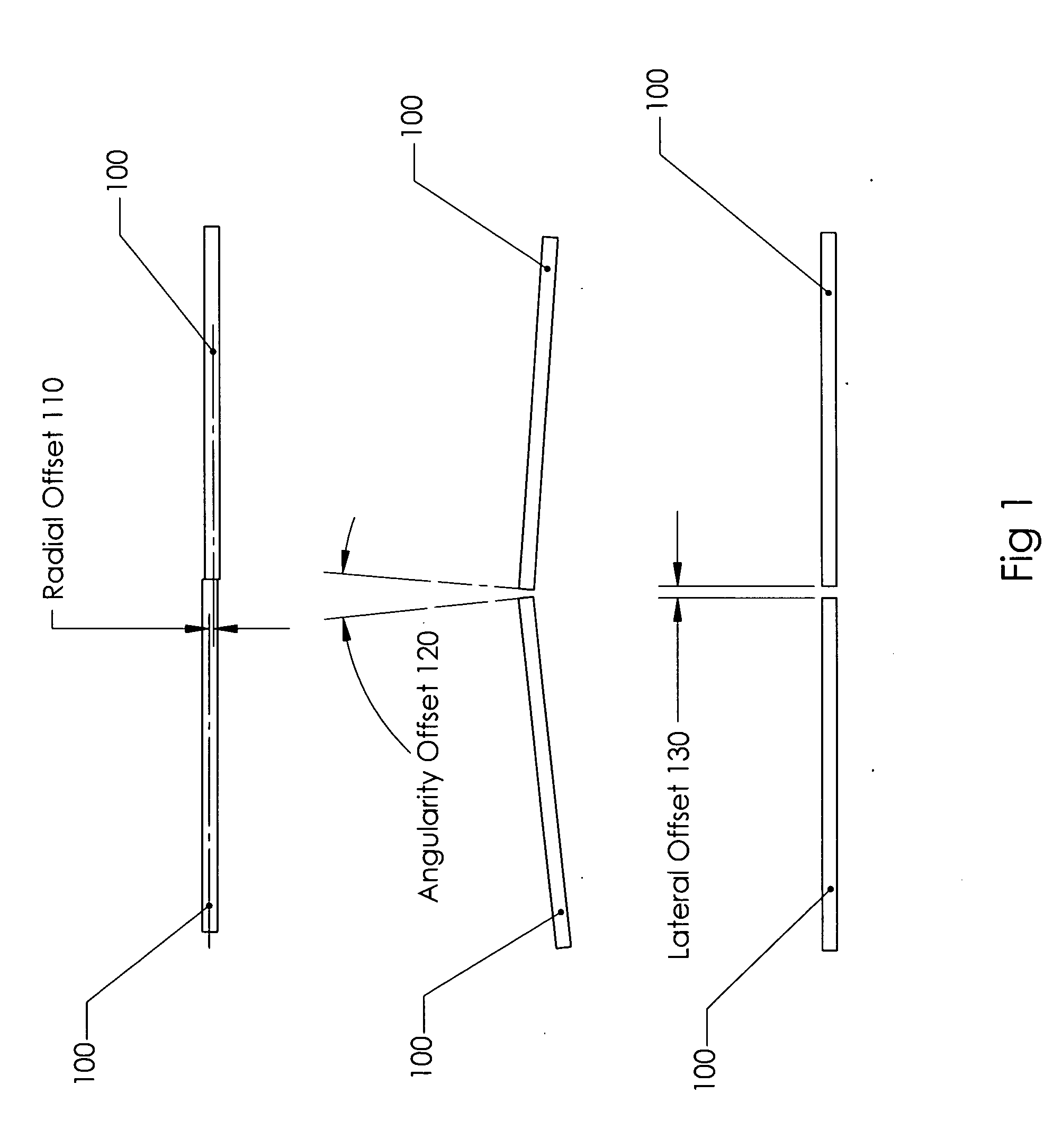
[0060]Normally, a long, straight and precise channel that matches the optical fiber size is needed to facilitate fiber optics cable mechanical splicing. FIG. 1 shows the necessary optics fibers' physical alignment requirements for coupling that will result in no / or minimum optical power loss. In the case of single mode optical fibers, the radial offset 110 should be less than 10% of the wave guide core diameter (generally 0.009 mm), i.e., less than 0.001 mm for single mode fiber optics. The angularity offset 120 should be 2 degrees or less, and the lateral offset 130 should be (20%) 0.002 mm or less. If these requirements are satisfied, the coupling loss will be within acceptable limits, i.e. limited to 0.3 dB or less.

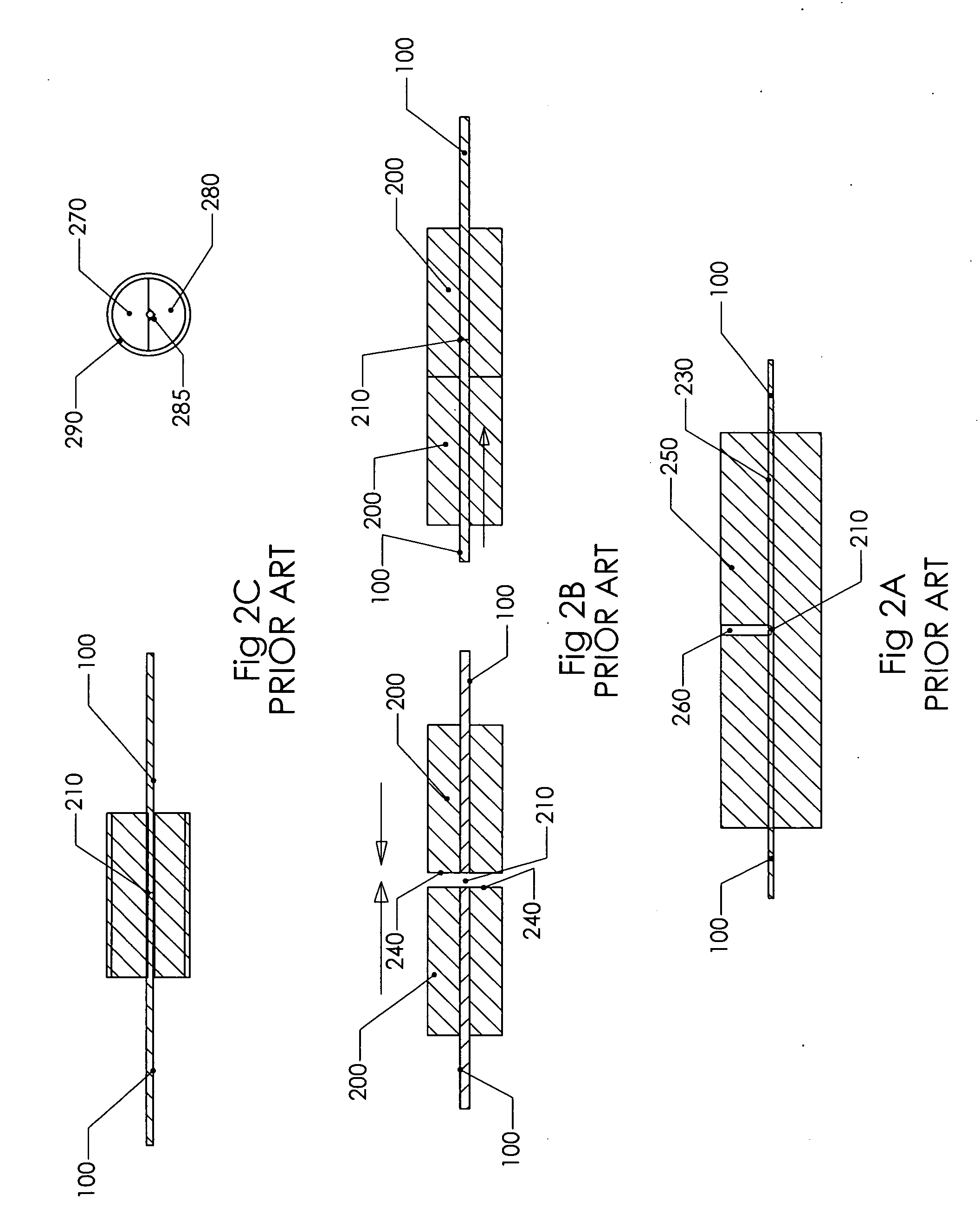
[0061]FIG. 2A illustrates a prior art mechanical splicer 250. Extensive effort was made to create a straight through bore hole 230. If the bore hole size 230 is too loose, then the fibers will not properly align and therefore will not meet fiber light optical coupling ...


PUM


Abstract

A three rod bundle confined inside a sleeve is constructed as a light guiding fiber mechanical splicing device which is stiff, strong and precise, with no moving parts. The design also applies to splicing fibers to pre-polished optical connectors through a built-in model of this innovative mechanical splicer. Applying the Soddy circles formula and using a bin approach assists in deriving the exact rod sizes needed and sleeve bore size to accommodate the three-rod bundle, so that this apparatus can be properly designed to guide any size of light guide fibers and studs with minimum clearance. Rods of varying diameters are sorted into bins and chosen based upon the aperture desired, thus eliminating the need for tight tolerance of the diameters of the three rods. This unique design allows for construction of a precision virtual hole of very long depth, which enables two optical fiber studs to butt against each other with a core to core misalignment of less than 1 um for single mode fiber optics cables. Unlike prior arts, the sleeve holding the rods eliminates the need for any clamping mechanism to tighten a loose bundle, which induces undesirable mechanical strain. It also eliminates the need to use a fiber clamp to force the fiber studs against dimensionally unstable V or U groove alignment features which also induce undesirable mechanical strain. A fiber holder is also presented to depict the usefulness of this invention on hold fiber in position.

Description

CROSS REFERENCE TO RELATED APPLICATION[0001]This application is a Continuation-in-Part of copending U.S. application Ser. No. 12 / 070,866, filed Feb. 21, 2008, and claims priority thereto.FIELD OF INVENTION[0002]The present invention relates to the field of optics fibers, and in particular to the essential process of mechanically splicing optics fibers with precise alignment. It also applies to optical connector terminations, optics fiber holding devices and optics fiber process holding methods.REFERENCES CITED [REFERENCED BY US PATENT DOCUMENTS][0003]Pat. No.Issue DateInventor3,989,567Nov. 2, 1976Tardy4,047,796Sept. 13, 1977Kao et al.4,123,139Oct. 31, 1978Sandahl4,223,976Sept. 23, 1980Zangiacomi et al4,378,145Mar. 29, 1983Stancati et al.4,460,243Jul. 17, 1984Strait, Jr.4,490,007Dec. 25, 1984Murata4,506,946Mar. 26, 1985Hodge4,575,182Mar. 11, 1986Hensel et al4,676,589Jun. 30, 1987Miyashita, et al.4,921,323May 1, 1990Delahanty, et al.6,981,802B2Jan. 3, 2006Sasaki, et al.6,779,931B2Aug....

Claims


Application Information

Patent Timeline
Patent Type & Authority Applications(United States)
IPC IPC(8): G02B6/38G02B6/00G02B6/255
CPCG02B6/3806G02B6/3841G02B6/3846G02B6/3882
Inventor WANG, WEI-MIN
Owner WANG WEI MIN
Why Eureka
Try Eureka