Compressor stage assembly lock

a compressor and assembly technology, applied in the direction of machines/engines, stators, liquid fuel engines, etc., can solve the problems of increased manufacturing costs associated with threaded holes, poor quality assembly, and increased turbocharger assembly costs, so as to minimize assembly and parts costs

Active Publication Date: 2007-11-08
GARRETT TRANSPORATION I INC
View PDF12 Cites 18 Cited by
  • Summary
  • Abstract
  • Description
  • Claims
  • Application Information

AI Technical Summary

Benefits of technology

[0013] An advantage of the present invention is that assembly and parts costs are minimized.
[0014] Other objects, advantages and novel features, and further scope of applicability of the present invention will be set forth in part in the detailed description to follow, taken in conjunction with the accompanying drawings, and in part will become apparent to those skilled in the art upon examination of the following or may be learned by practice of the invention. The objects and advantages of the invention may be realized and attained by means of the instrumentalities and combinations particularly pointed out in the appended claims.
[0015] The accompanying drawings, which are incorporated into, and form a part of, the specification, illustrate one or more embodiments of the present invention and, together with the description, serve to explain the principles of the invention. The drawings are only for the purpose of illustrating one or more preferred embodiments of the invention and are not to be construed as limiting the invention. In the drawings:
[0016]FIG. 1 is a cross section view of a turbocharger of the prior art;
[0017]FIG. 2 is a close-up cross section view of an embodiment of the present invention showing a turbocharger compressor housing comprising a retaining ring used to secure the compressor housing to a backplate;
[0018]FIG. 3 is a close-up cross section view of an embodiment of the present invention showing a turbocharger backplate comprising a retaining ring used to secure a turbocharger compressor to the backplate;

Problems solved by technology

Therefore, there exists a potential for poor quality assembly as a result of the application of improper torque on the assembly fasteners.
There are also greater turbocharger assembly costs as a result of using clamp plates and bolts and greater manufacturing costs associated with threaded holes.

Method used


Image

  • Compressor stage assembly lock
  • Compressor stage assembly lock
  • Compressor stage assembly lock

Examples


Embodiment Construction

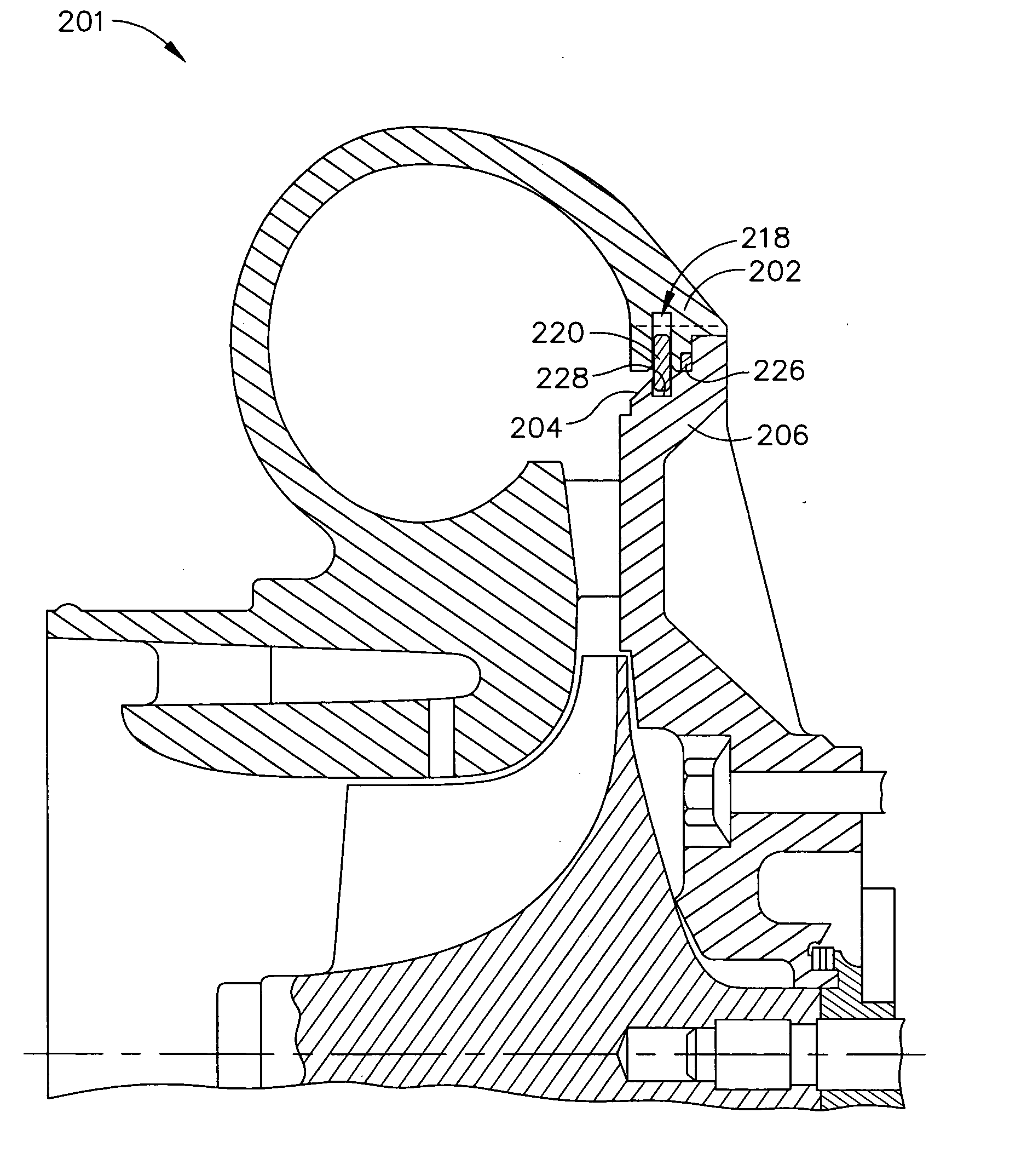
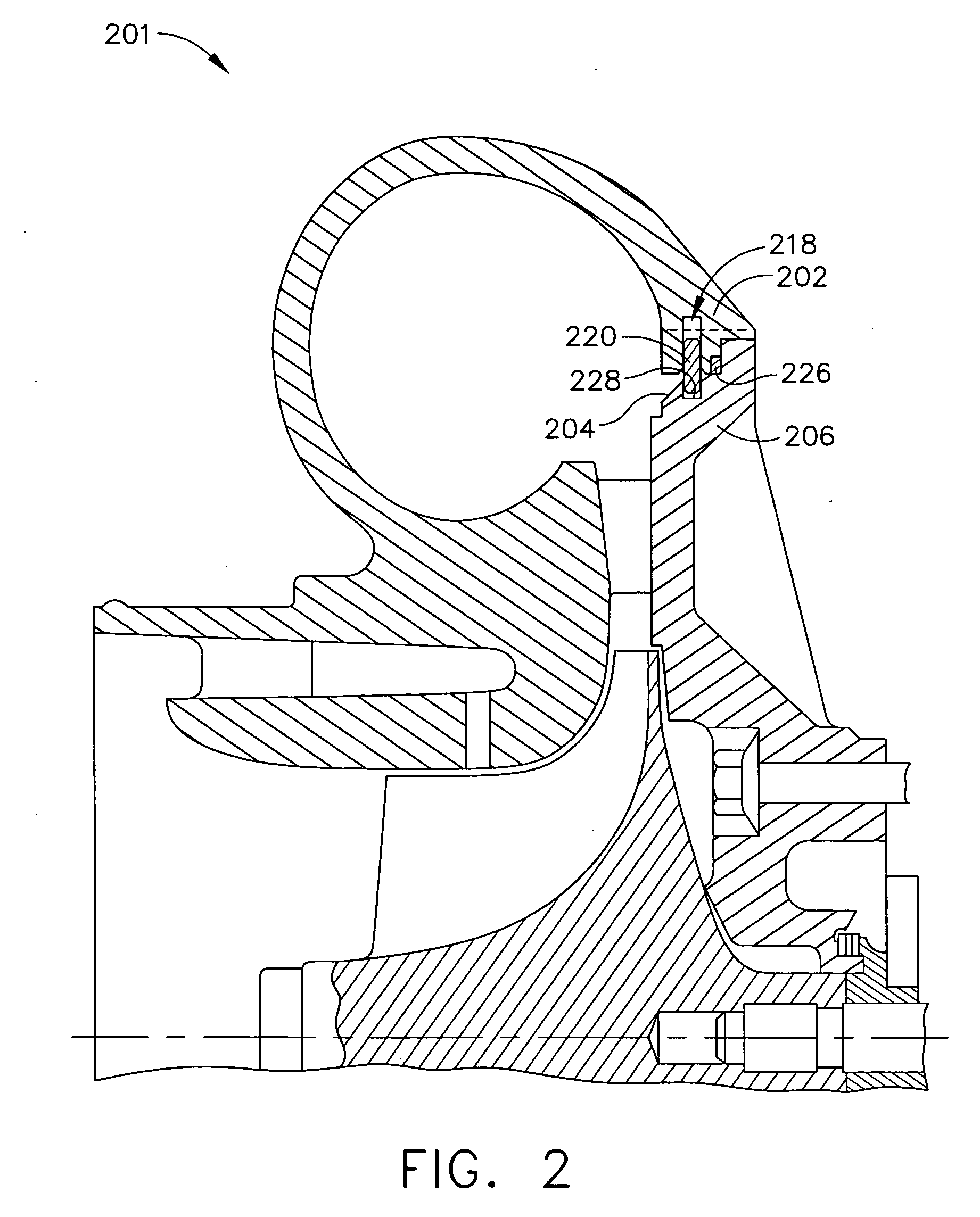
[0021] The present invention provides a turbocharger assembly lock comprising a retaining ring and circumferential grooves for attaching turbocharger stages (i.e., stage components) such as, but not limited to, a compressor, a turbine, and / or a center housing rotating assembly to each other. Thus, the present invention comprises a retaining ring and grooves disposed in the turbocharger stages for attaching the turbocharger stages to each other. For example, an embodiment of the present invention comprises a retaining ring to attach a compressor stage to a center housing rotating assembly (“CHRA”). Also, the retaining ring of the present invention is applicable to single stage compressors and two stage compressor assemblies. As used in the specification and claims herein, the terms “a”, “an”, and “the” mean one or more.

[0022] Therefore, although the description and figures depict, for illustrative purposes, the attachment of a compressor stage to another turbocharger stage, it is un...


PUM


Abstract

The present invention relates to a turbocharger assembly lock comprising a retaining ring partially disposed in a circumferential groove of a first turbocharger stage component and partially in a circumferential groove of a second turbocharger stage component so that the turbocharger stages are securely attached to each other.

Description

CROSS-REFERENCES TO RELATED APPLICATIONS [0001] Not Applicable. BACKGROUND OF THE INVENTION [0002] 1. Field of the Invention (Technical Field) [0003] The present invention relates to turbocharger compressor assemblies, particularly to means for attaching one turbocharger stage component, such as a compressor assembly, to another stage component, such as a second compressor assembly or a turbocharger center housing rotating assembly. [0004] 2. Description of Related Art [0005] Note that where the following discussion refers to a number of publications by author(s) and year of publication, because of recent publication dates certain publications are not to be considered as prior art vis-a-vis the present invention. Discussion of such publications herein is given for more complete background and is not to be construed as an admission that such publications are prior art for patentability determination purposes. [0006] Turbochargers for pressurizing or boosting the intake air stream int...

Claims


Application Information

Patent Timeline
Patent Type & Authority Applications(United States)
IPC IPC(8): F02B33/44
CPCF01D25/24F02C6/12F05D2230/52F05D2230/60F05D2220/40
Inventor MARTIN, STEVEN P.MEADE, CHRISTOPHER O.MCGRAW, ANDREW F.
Owner GARRETT TRANSPORATION I INC
Why Eureka
Try Eureka