Device for imaging and observing an eye at a selectable image scale

a selectable image scale and eye technology, applied in the field of eye examination devices, can solve the problems of not providing for changing the optical imaging scale, complicated adjustment of optics, etc., and achieve the effect of minimizing the effort required for adjustment and assembly

Inactive Publication Date: 2007-08-21
CARL ZEISS MEDITEC AG
View PDF6 Cites 0 Cited by
  • Summary
  • Abstract
  • Description
  • Claims
  • Application Information

AI Technical Summary

Benefits of technology

[0010]It is the primary object of the present invention to develop a solution for displaying and observing an eye in which imaging scales are selectable without making the basic construction of the device overall substantially more complicated and bulky. Further, the effort required for adjustment and assembly is minimized.

Problems solved by technology

The disadvantage of this application consists primarily in the complicated adjustment of the optics and in the fact that the mechanical movement must be carried out very exactly.
The disadvantage in this device is that it does not provide for changing the optical imaging scale.

Method used


Image

  • Device for imaging and observing an eye at a selectable image scale
  • Device for imaging and observing an eye at a selectable image scale

Examples


Embodiment Construction

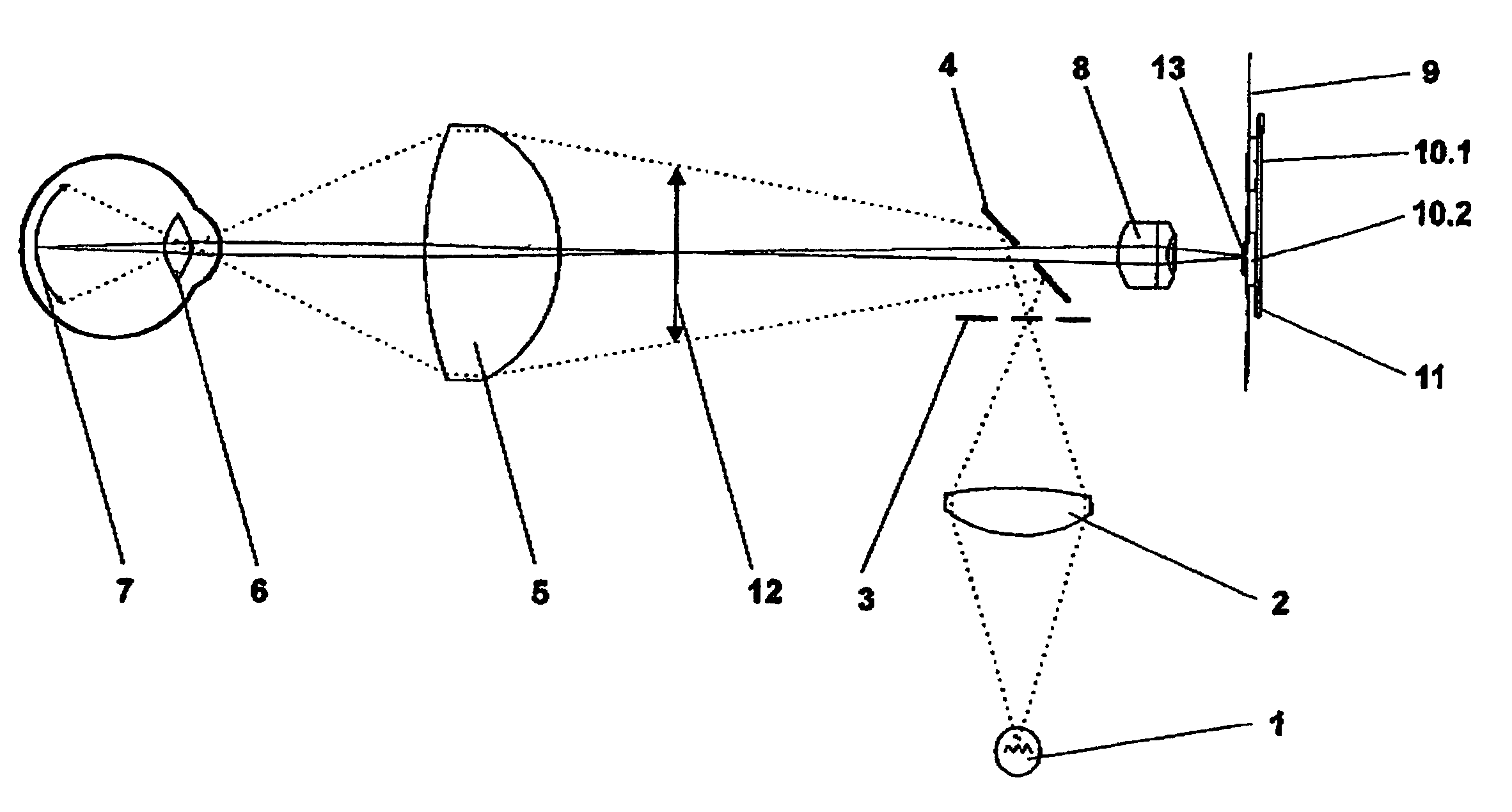
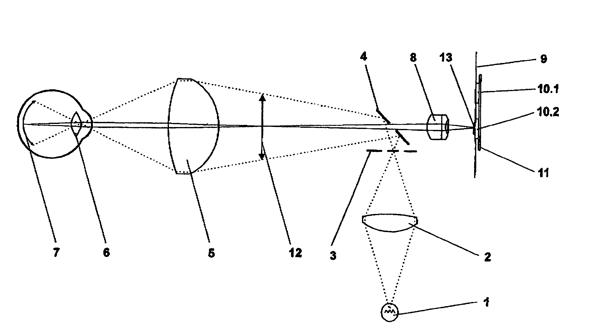
[0016]In the device according to the invention for displaying and observing an eye with selectable imaging scale, at least two image recording sensors with different shape factors are swivelably arranged in the imaging plane of the device.

[0017]The different shape factors can be realized by optically active surfaces of the image recording sensors of identical geometrical size with a different quantity of pixels. The image recording sensors which are swivelably arranged in the imaging plane preferably have an approximately identical numbers of pixels with optically active surfaces of different sizes. This has the advantage that the electronic control and evaluation for the image recording sensors are identical.

[0018]The image recording sensors arranged in the imaging plane can be introduced into the beam path by a lateral movement as well as by a circular movement. The cable feed is considerably simplified in the case of a lateral movement.

[0019]FIG. 1 shows the basic construction of...


PUM


Abstract

The present invention is directed to a device for examining the eye, preferably the fundus of the eye, by an optical system and electronic sensors for image recording in different imaging scales. In the device according to the invention, at least two image recording sensors with different shape factors are swivelably arranged in the imaging plane of the device. These image recording sensors have optically active surfaces of different geometric sizes, an approximately identical number of pixels and preferably the same electronic control and evaluation. The invention described herein requires no additional objectives and the optical adjustment is limited to an individual rigid objective. An exact alignment of the image recording sensors in the imaging plane and manufacturing tolerances can be compensated by adapting the image section by means of software. It is particularly advantageous that the imaging scale is influenced without changing the optical parameters of the system.

Description

CROSS-REFERENCE TO RELATED APPLICATIONS[0001]This application claims priority of International Application No. PCT / EP2004 / 005767, filed May 28, 2004, and German Application No. 103 26 510.4, filed Jun. 6, 2003, the complete disclosures of which are hereby incorporated by reference.BACKGROUND OF THE INVENTION[0002]a) Field of the Invention[0003]The present invention is directed to a device for examining the eye, preferably the fundus of the eye, by means of an optical system and electronic sensors for image recording, wherein sectional enlargements of the recordings are possible by means of changing the imaging scale.[0004]b) Description of the Related Art[0005]According to the known prior art, the imaging scale in devices of the type mentioned above is usually changed by optical means which are swiveled into and out of the beam path in addition to or in exchange with one another.[0006]The Laid Open Application DE 24 35 548 describes an optical system for photographing the retina wit...

Claims


Application Information

Patent Timeline
Patent Type & Authority Patents(United States)
IPC IPC(8): A61B3/14
CPCA61B3/145
Inventor MOHR, THOMASBIERNAT, DETLEF
Owner CARL ZEISS MEDITEC AG
Why Eureka
Try Eureka