Ignition device

Active Publication Date: 2019-05-30
PRUFREX ENG E MOTION
View PDF9 Cites 0 Cited by
  • Summary
  • Abstract
  • Description
  • Claims
  • Application Information

AI Technical Summary

Benefits of technology

[0007]It is therefore an object of the present invention to provide an ignit

Problems solved by technology

The disadvantage here are costs incurred due to the relatively high cabling or assembly costs and due to

Method used


Image

  • Ignition device
  • Ignition device
  • Ignition device

Examples


Embodiment Construction

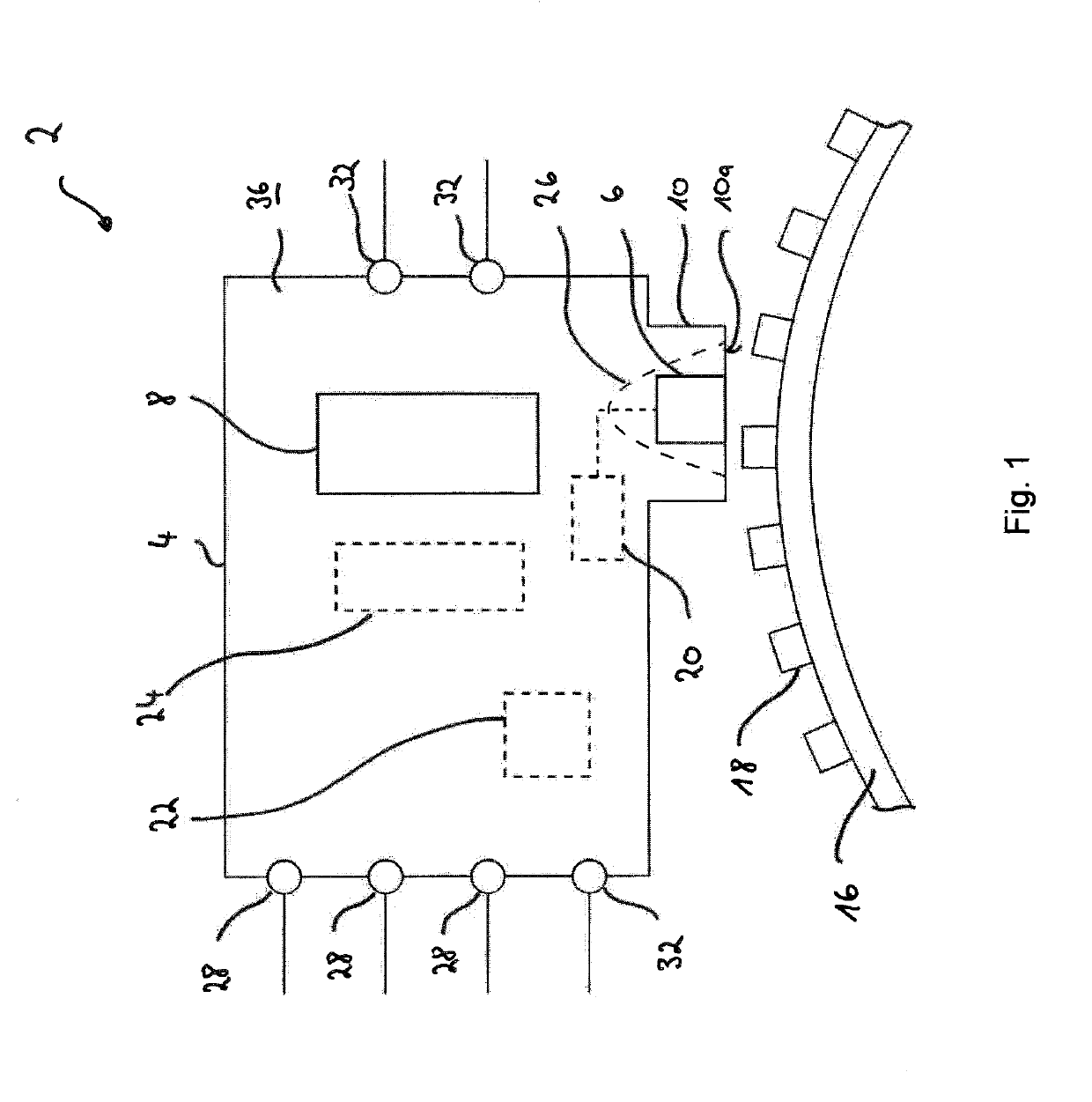
[0047]FIG. 1 shows a schematic representation of an ignition device 2. This comprises a housing 4, in which a crankshaft sensor 6 and an ignition transformer arrangement 8 are accommodated. The crankshaft sensor 6 is designed as a Hall sensor. Further, said sensor is arranged in a housing pocket 10, which faces a crankshaft 14 in the assembled state of the ignition device 2 on an internal combustion engine 12 (FIG. 7). In summary, a pocket bottom 10a of the housing pocket 10 is arranged on the crankshaft side. In this case, a position sensor 16 with teeth 18 is coupled to the crankshaft 14 so that the teeth are adjusted during a rotation of the crankshaft 14 by a sensitive region of the crankshaft sensor 6. This adjustment movement produces a voltage signal of the Hall sensor, which is recorded as a measured value(s). By means of the measured values, the rotational speed and / or position of the crankshaft 14 is detected. In this case, at least one tooth 18 is omitted for reference pu...


PUM


Abstract

An ignition device for an internal combustion engine, having a housing in which a crankshaft sensor is accommodated for detecting the rotational speed and/or the position of a crankshaft, which is in particular provided with a toothed position sensor and in which at least one ignition transformer with a primary winding is accommodated, and a secondary winding for generating a spark for the internal combustion engine is accommodated, wherein a number of input ports, in particular for the connection of an electrical energy source for supplying the or each ignition transformer and/or for supplying sensor and/or control signals, and in which a plurality of output ports, in particular for connecting at least one spark plug and/or for emitting control signals, are provided.

Description

[0001]This nonprovisional application claims priority under 35 U.S.C. § 119(a) to German Patent Application No. 10 2017 221 448.1, which was filed in Germany on Nov. 29, 2017, and which is herein incorporated by reference.BACKGROUND OF THE INVENTIONField of the Invention[0002]The present invention relates to an ignition device for an internal combustion engine.Description of the Background Art[0003]An internal combustion engine designed as a small engine, such as a small engine of a lawn mower or a power generator, in particular has a system for an ignition function and for electronic fuel injection or for mixture control. In particular, a small engine here is understood to be a two-stroke engine with a capacity of up to 350 cm3 and / or a four-stroke engine with one or two cylinders and a capacity of up to 1000 cm3.[0004]Such systems include a number of individual components. For example, included are ignition coils, injection valves, gasoline pumps, speed sensors, temperature sensor...

Claims


Application Information

Patent Timeline
IPC IPC(8): F02P5/15F02P5/04F02P13/00
CPCF02P5/151F02P5/045F02P13/00F02P3/0407F02P7/03F02P7/07
Inventor LAJDA, MAREKHEUBECK, JOCHEN
Owner PRUFREX ENG E MOTION
Why Eureka
Try Eureka