Turnover mechanism
A technology of flipping mechanism and rotating shaft, which is used in measuring devices, material analysis by optical means, instruments, etc., can solve problems such as excessive flipping angle, inaccurate positioning, and error in motor operation, and achieves reduction in volume and Cost, stable operation effect
- Summary
- Abstract
- Description
- Claims
- Application Information
AI Technical Summary
Problems solved by technology
Method used
Image
Examples
Embodiment 1
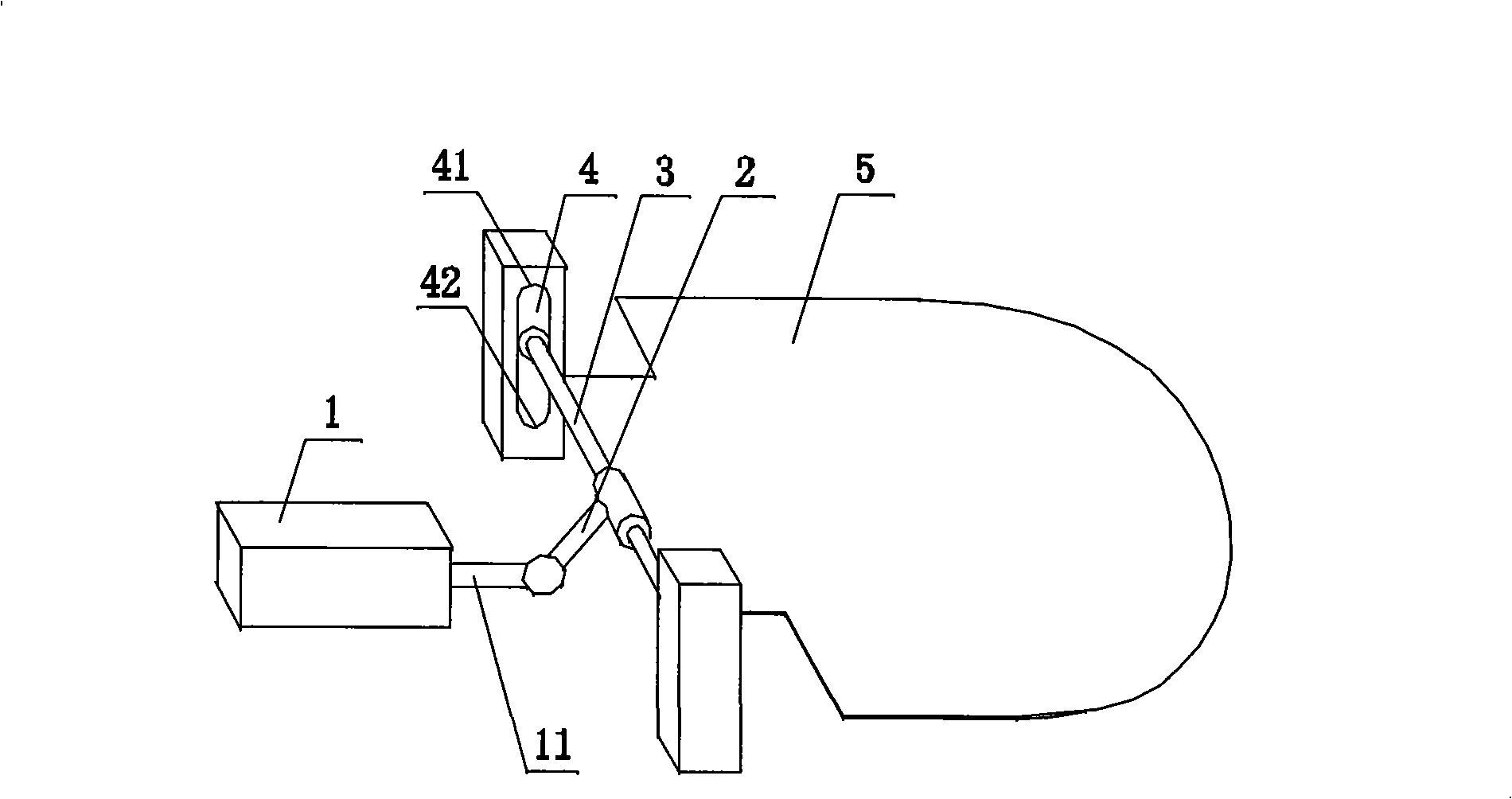
[0048] Such as image 3 , Figure 4 , Figure 5 As shown, a turning mechanism is used in an infrared detection instrument, including a driving device 1 , a rotating device and a turning plate 5 . The rotating device is composed of a rotating arm 2 , a rotating shaft 3 and a first limiting groove 4 . The turning plate 5 is installed on the rotating shaft 3 and remains relatively fixed; the rotating arm 2 is fixedly installed on the rotating shaft 3; the two ends of the rotating shaft 3 are located at the first vertical limit In the groove 4; the driving device 1 is installed horizontally, and the present embodiment adopts a cylinder, wherein the telescopic arm 11 is movably connected with the rotating arm 2, such as a hinge connection.
[0049]The vertical distance from the connecting point between the rotating arm 2 and the telescopic arm 11 to the rotating shaft 3 is 1. Since the turning plate 5 is installed on the rotating shaft 3, the turning plate 5 and the rotating sha...
Embodiment 2
[0055] Such as Image 6 , Figure 7 , Figure 8 As shown, an overturning mechanism is used in infrared detection instruments. The difference from the overturning mechanism in Embodiment 1 is that the overturning mechanism also includes a horizontally installed second limiting groove 6, and the telescopic arm 11 is connected to the The connection between the rotating arms 2 is also provided with a limiter 12, and the two ends of the limiter 12 are located in the second limiter groove 6, which ensures that the telescopic arm 11 only moves linearly in the horizontal direction. The service life of the driving device 1 is prolonged.
[0056] The vertical distance from the connecting point of the rotating arm 2 and the telescopic arm 11 to the rotating shaft 3 is 1, and the range of the included angle α between the plane where the rotating arm 2 and the rotating shaft 3 are located and the turning plate 5 is (90 °, 180°), while also satisfying: cot α ...
Embodiment 3
[0063] Such as Figure 9 As shown, a turning mechanism is used to turn the object over 180°. The difference from the turning mechanism in Embodiment 2 is that in this embodiment, γ is 97°, and β=7°, that is, the turning plate 5 starts from Flip 97° in the horizontal direction, satisfying the condition α∈(90°, 180°), cot α ≥ - 1 + sin β cos β , The range of the included angle α for α-β>90° is (97°, 138.5°], and the included angle α is 138° in this embodiment.
[0064] The vertical distance from the connection point between the rotating arm 2 and the telescopic arm 11 to the plane where the bottom end 42 of the first limiting groove 4 is located is lcos[180°-(α-β)]. This design ensures that when When the two ends of the rotating shaft 3 move to the bottom end 42 in the first limiting groove 4, t...
PUM
 Abstract
Description
Claims
Application Information
 - R&D
- Intellectual Property
- Life Sciences
- Materials
- Tech Scout
- Unparalleled Data Quality
- Higher Quality Content
- 60% Fewer Hallucinations
Browse by: Latest US Patents, China's latest patents, Technical Efficacy Thesaurus, Application Domain, Technology Topic, Popular Technical Reports.
© 2025 PatSnap. All rights reserved.Legal|Privacy policy|Modern Slavery Act Transparency Statement|Sitemap|About US| Contact US: help@patsnap.com


