Pneumatic brake cylinder and brake clamp unit

A pneumatic braking and cylinder head technology, applied in the field of rail transit, can solve the problems of increased volume of the brake caliper unit, limited space for braking air pressure, and no braking force amplifying mechanism. The effect of small force, volume and weight

Active Publication Date: 2021-05-28
CRRC QINGDAO SIFANG ROLLING STOCK RES INST
View PDF6 Cites 2 Cited by
  • Summary
  • Abstract
  • Description
  • Claims
  • Application Information

AI Technical Summary

Problems solved by technology

Due to the limitation of installation size and space, there is no room for increasing the diameter of the brake cylinder piston, and the existing direct-acting brake cylinder does not have a brake force amplification mechanism in the brake cylinder. If you want to increase the brake caliper unit The brake ratio can only increase the leverage ratio, but it will increase the volume of the entire brake caliper unit, an

Method used


Image

  • Pneumatic brake cylinder and brake clamp unit
  • Pneumatic brake cylinder and brake clamp unit
  • Pneumatic brake cylinder and brake clamp unit

Examples


Embodiment 1

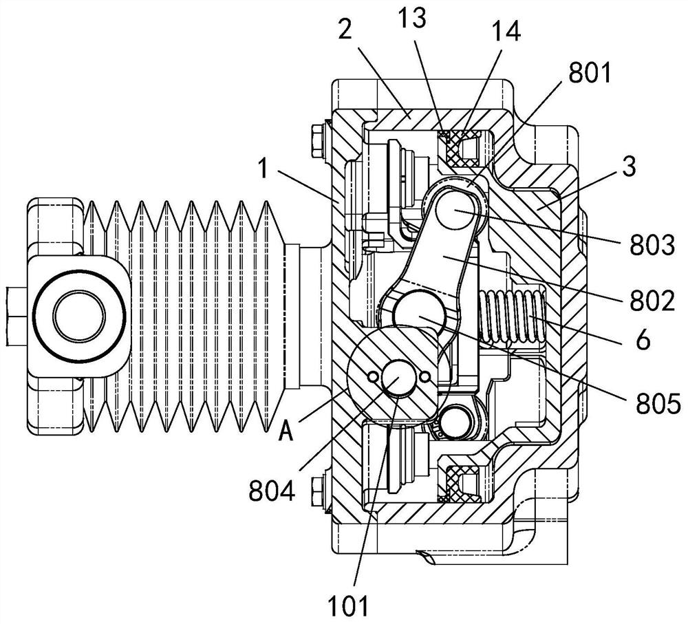
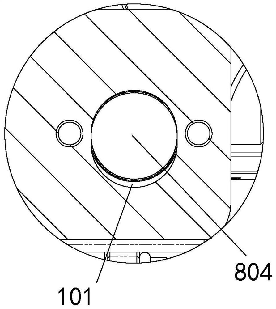
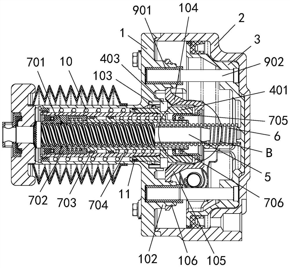
[0067] Embodiment 1: see figure 1 , image 3 , Figure 6 , a pneumatic brake cylinder, comprising:

[0068] cylinder head 1;

[0069] The rear cover 2 is connected with the cylinder head 1 and forms a sealed cavity with the cylinder head 1;

[0070] The piston 3 is located in the sealed chamber;

[0071] The pushing part assembly is arranged in the sealed cavity and is slidably connected with the cylinder head 1;

[0072] Lead screw 5 is sleeved in the push part assembly;

[0073] Adjust the spring 6, one end is pressed on the piston, and the other end is pressed on the lead screw;

[0074] The gap adjustment mechanism is located between the pusher component and the lead screw 5;

[0075] Two amplifying mechanisms are arranged symmetrically around the circumference, and the amplifying mechanisms include:

[0076] Bearing 801 abuts against piston 3;

[0077] One end of the lever 802 is pivotally connected to the bearing 801, the other end is pivotally connected to the ...

Embodiment 2

[0112] Example 2: see Figure 10 , the present embodiment provides a brake caliper unit, including a caliper arm assembly 15 and a pneumatic brake cylinder 16, the pneumatic brake cylinder 16 is hinged to the caliper arm of the caliper arm assembly 15 through a connecting bolt 17, the The pneumatic brake cylinder 16 adopts the pneumatic brake cylinder described in Embodiment 1. Wherein, the clamp arm acts as a force transmission lever, and the braking output force of the pneumatic brake cylinder 16 is transmitted to the brake pad holder 18 through the clamp arm.

[0113] The brake caliper unit described in this embodiment adopts the pneumatic brake cylinder described in the embodiment, which not only has a high braking ratio, but also reduces the volume of the brake caliper unit, and the installation space is small.

[0114] In this embodiment, the brake caliper unit is installed on the bogie frame of the rail transit vehicle, and the brake disc is held tightly by the brake p...


PUM


Abstract

The invention relates to a pneumatic brake cylinder and a brake clamp unit. The pneumatic brake cylinder comprises a cylinder cover, a rear cover, a piston, a pushing part assembly, a lead screw, an adjusting spring, a gap adjusting mechanism and at least two amplifying mechanisms; the rear cover is connected with the cylinder cover and forms a sealing cavity with the cylinder cover; the piston is arranged in the sealing cavity; the pushing part assembly is arranged in the sealing cavity and is in sliding connection with the cylinder cover; the lead screw is arranged in the pushing part assembly in a sleeving manner; one end of the adjusting spring is pressed on the piston, and the other end of the adjusting spring is pressed on the lead screw; the gap adjusting mechanism is arranged between the pushing part assembly and the lead screw; the at least two amplifying mechanisms are circumferentially and symmetrically arranged, and each amplifying mechanism comprises a bearing and a lever, wherein the bearings are attached to the piston; and one ends of the levers are coupled with the bearings, the other ends of the levers are coupled with the cylinder cover, and the middles of the levers are coupled with the pushing part assembly. According to the pneumatic brake cylinder and the brake clamp unit, the internal space of the brake cylinder can be saved and the volume of the brake cylinder can be reduced on the premise of the same brake multiplying power.

Description

technical field [0001] The invention belongs to the technical field of rail transit, and relates to rail vehicle braking technology, in particular to a pneumatic brake cylinder and a brake caliper unit. Background technique [0002] With the development of rail transit equipment technology, more and more equipment is installed on the bogie, and the space is becoming more and more compact, which requires the brake caliper unit to be smaller and lighter. At the same time, as the running speed of the train increases, the braking force output by the brake caliper unit is required to be greater, and the number of brake caliper units is also increasing. At present, 3 sets of axle-mounted brake caliper units are installed on each axle of the high-speed EMU. The distance between the 3 sets of brake caliper units is very small when the wear is limited, and even in some extreme working conditions. Collision interference occurs. [0003] The braking output force of the brake caliper ...

Claims


Application Information

Patent Timeline
IPC IPC(8): F16D65/18F16D65/00F16D121/04
CPCF16D65/18F16D65/0075F16D2121/04
Inventor 孟庆余覃立伟王令军王风洲刁有彬徐少亭
Owner CRRC QINGDAO SIFANG ROLLING STOCK RES INST
Why Eureka
Try Eureka