
Optical encoder device for small-sized motor

A technology of optical encoders and small motors, applied in the direction of electrical components, electromechanical devices, electric components, etc., can solve the problems of feasibility and positioning accuracy, and the lack of optical sensor modules, etc., to achieve structural robustness, high Effect of positioning accuracy, reliable positioning and fixation

Active Publication Date: 2008-10-15
MABUCHI MOTOR
View PDF2 Cites 5 Cited by
  • Summary
  • Abstract
  • Description
  • Claims
  • Application Information

AI Technical Summary

Problems solved by technology

However, conventional encoding devices do not have a part for structurally positioning the light sensor module
Therefore, conventional encoding devices require external positioning using jigs or the like, and the feasibility and positioning accuracy associated with this is worrying

Method used


Image

  • Optical encoder device for small-sized motor
  • Optical encoder device for small-sized motor
  • Optical encoder device for small-sized motor

Examples


Embodiment Construction

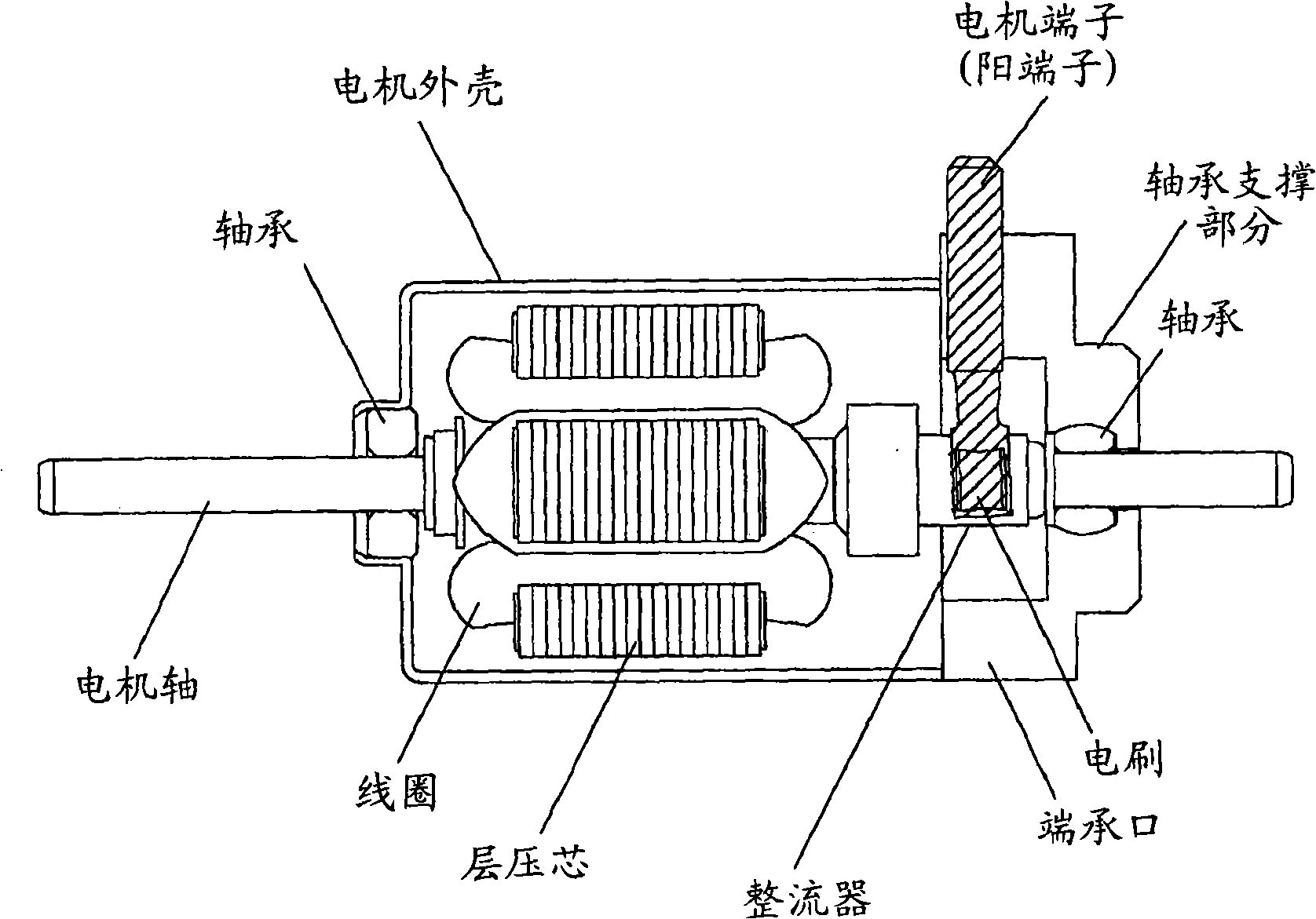
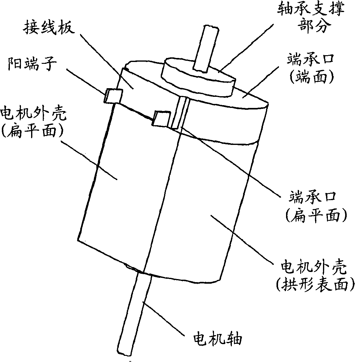
[0012] The invention will now be described by means of examples. Figure 1A Just a cross-sectional view of the motor, positioned so that the flat surface is facing up in this drawing, from which the motor terminals (male terminals) protrude; Figure 1B is a perspective view of the motor viewed from the outside of the motor. A pair of magnets, serving as stator poles, are fixed to the inner surface of the arcuate wall portion of the motor housing made of metal. The rotor is rotatably fixed on the motor housing. The rotor is constructed by integrally assembling a commutator and rotor poles formed from laminated cores and coils onto a motor shaft. The motor housing has flat wall portions (flat faces) on opposite sides and arched wall portions extending between the flat wall portions, so that the motor housing has a bottomed hollow tubular shape as a whole. After the rotor integrally assembled to the motor shaft is inserted into the motor case through its opening, an end socket...


PUM


Abstract

A photo sensor module includes a holder made of resin and a light-emitting element and a light-receiving element accommodated in the holder. A printed circuit board is fixed to a flat side wall portion of a motor. The resin holder has a guide portion which is formed integrally therewith and which comes into contact with an end surface and a bearing-holding portion of an end bell. The printed circuit board is fixed in a state in which the guide portion is sandwiched between the bearing-holding portion and the printed circuit board while being brought into contact with the end surface of the end bell, whereby the photo sensor module is positioned in thrust and radial directions of the motor.

Description

technical field [0001] The present invention relates to optical encoder devices for small motors that optically detect the rotation of the motor shaft. Background technique [0002] In some cases, there is a need for a device connected to a small motor for detecting the rotational speed and position of said motor. Small motors equipped with optical encoder devices used as detection devices have been used in devices that require rotation control, such as self-driving electric components and office automation equipment such as printers. [0003] Figure 8 A conventional technique of connecting an optical encoder device to a motor is shown (see Japanese Patent Application Laid-Open No. 2003-199297). Such as Figure 8 As shown, on the flat side surface of the motor ( Figure 8 A pair of through holes are formed on the lower surface in the middle to connect to the printed circuit board. The printed circuit board includes a pair of contact posts adapted to be inserted into the p...

Claims


Application Information

Patent Timeline
Patent Type & Authority Applications(China)
IPC IPC(8): H02K11/00
CPCH02K11/0026H02K5/225H02K2211/03H02K11/22
Inventor 五十岚公平
Owner MABUCHI MOTOR
Features
  • Generate Ideas
  • Intellectual Property
  • Life Sciences
  • Materials
  • Tech Scout
  • Unparalleled Data Quality
  • Higher Quality Content
  • 60% Fewer Hallucinations
Learn More