Fluid pressure shock absorber

一种流体压力、缓冲器的技术,应用在减振器、减震器、弹簧/减震器等方向,能够解决低速区域衰减力大、降低主阀耐久性、难主阀开阀等问题,达到稳定衰减力、提高耐久性的效果

Inactive Publication Date: 2008-10-22
HITACHI AUTOMOTIVE SYST LTD
View PDF1 Cites 11 Cited by
  • Summary
  • Abstract
  • Description
  • Claims
  • Application Information

AI Technical Summary

Problems solved by technology

[0003] In the above-mentioned existing hydraulic shock absorber, the damping force in the low-speed region where the piston speed is low depends on the oil passage area of ​​the orifice, and the damping force in the high-speed region depends on the preset valve opening pressure of the disc valve. Therefore, There are the following problems: the degree of freedom in setting the damping force characteristics is low; if you want to obtain a small damping force in the low-speed area where the piston speed is low, the damping force in the high-speed area is insufficient; if you want to obtain a large damping force in the high-speed area, the Excessive damping force in the low speed range
In the extremely low speed region where the piston speed is extremely low, the pressure introduced through the check valve cannot sufficiently increase the pressure of the back pressure chamber, so it is difficult to reliably prevent the main valve from opening, and the damping force is likely to be unstable.
In addition, the back pressure chambers on both the expansion side and the contraction side are pressurized in both the expansion and contraction strokes, and the load is repeatedly applied to the main valve accordingly, so the durability of the main valve is reduced.

Method used


Image

  • Fluid pressure shock absorber
  • Fluid pressure shock absorber
  • Fluid pressure shock absorber

Examples


Embodiment Construction

[0036] Embodiments of the present invention will be described in detail below based on the drawings.

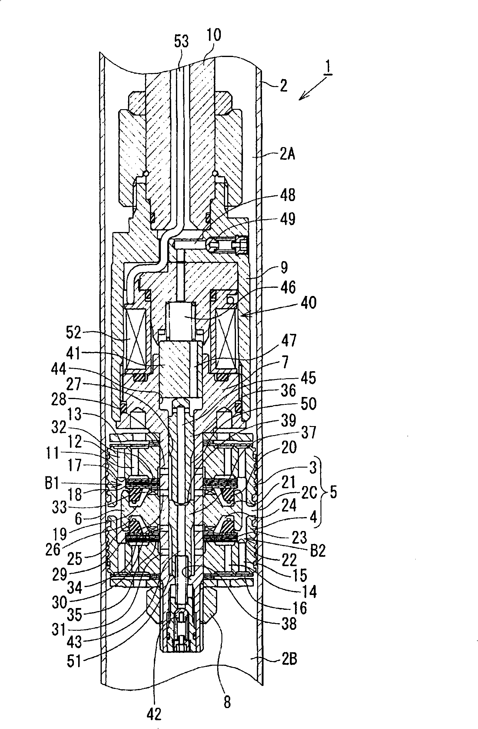
[0037] refer to figure 1 The first embodiment of the present invention will be described. Such as figure 1 As shown, the damping force adjustable hydraulic shock absorber 1 (fluid pressure shock absorber) of this embodiment is a cylindrical hydraulic shock absorber, and a piston 5 composed of a first piston 3 and a second piston 4 is slidably embedded in the The cylinder 2 is divided by the piston 5 into two chambers, an upper cylinder chamber 2A and a cylinder lower chamber 2B, and a piston chamber 2C is formed between the first and second pistons 3 and 4 . The first and second pistons 3 , 4 are inserted into a front end portion of a hollow piston bolt 7 and integrally fixed by a nut 8 together with a valve member 6 sandwiched therebetween. A substantially bottomed cylindrical housing 9 is attached to a root end portion (upper portion in the drawing) of the piston bolt 7 ...


PUM


Abstract

An object of the present invention is to generate a stable damping force and enhance durability of a main valve in a hydraulic shock absorber in which valve opening of the main valve is controlled by an inner pressure of a backpressure chamber. A first piston 3 and a second piston 4 coupled to a piston rod 10 are fitted in a cylinder 2 such that a piston chamber 2 C is defined between the first and second pistons 3, 4 . An extension-side main valve 18 and a compression-side main valve 23 are provided in the piston chamber 2 C. Valve opening of the main valves is controlled by an extension-side backpressure chamber 19 and a compression-side backpressure chamber 24 . A compression-side check valve 13 and an extension-side check valve 16 are provided at the first piston 3 and the second piston 4 .; During an extension stroke of the piston rod 10 , the compression-side check valve 13 is closed, whereby action of a pressure of a cylinder upper chamber 2 A on the compression-side main valve 23 is prevented. During a compression stroke of the piston rod 10 , the extension-side check valve 16 is closed, whereby action of a pressure of a cylinder lower chamber 2 B on the extension-side main valve 18 is prevented. Accordingly, it is possible to generate a stable damping force, and enhance durability of the extension-side main valve 18 and the compression-side main valve 23.

Description

technical field [0001] The present invention relates to a fluid pressure damper such as an oil damper mounted on a suspension device of a vehicle such as a motor vehicle, and more particularly to a fluid pressure damper having a back pressure chamber that controls the flow of a main valve that generates a damping force valve opening pressure. Background technique [0002] Generally, a cylinder-type hydraulic shock absorber mounted on a suspension device of a vehicle such as a motor vehicle has a piston connected to a piston rod slidably embedded in a cylinder filled with oil, and a throttling valve is provided on the piston part. A damping force generating mechanism composed of holes and disc valves. The orifice and disc valve are used to control the flow of oil produced by the sliding of the piston in the cylinder with the expansion and contraction of the piston rod to generate damping force. In the low-speed region where the piston speed is low, the orifice produces a da...

Claims


Application Information

Patent Timeline
Patent Type & Authority Applications(China)
IPC IPC(8): F16F9/34
CPCF16F9/465F16F9/3485F16F9/32F16F9/34
Inventor 山口裕之片山洋平羽山弘之根津隆
Owner HITACHI AUTOMOTIVE SYST LTD
Why Eureka
Try Eureka